
Kuchora
BACKGROUND // Awhile back, I built a hanging pen plotter that suspended from two strings and drew images with dry erase markers. The hope was to build a display could be used in a storefront, a café menu board, or building lobby to display high fidelity images and messages without the perpetual energy usage of an LCD display. It was mesmerizing and engaging but also quite finnicky and slow and had some functional limitations. I wanted to build a more user friendly and commercially viable product that built of what I had learned from this first iteration.
A couple years after I built the Hangbot, a company by the name of Scribit built a hanging wall plotter that was very similar to my original prototype, with a few valuable differences. Though it was a more finished product that what I had created, it made me realize that the hanging plotter had some fundamental limitations that clearly couldn’t be overcome, but the idea of what the Scribit represented was validated by their $1.6 million Kickstarter. My hope with this new project was to take my learnings from my previous project and the work that Scribit has done, to build a better version of a device that served the same vision of providing a way for regular people to employ the whimsy of computer numeric control to augment their everyday lives.
Graphics part of a collaboration with Adrienne Baer.
OBJECTIVE // To build a low cost pen plotter display that dynamically draws images to be statically displayed in a user friendly, non-technical way.
DESIGN CRITERIA // Looking back at the hanging pen plotter that I built, and what I’ve seen about the Scribit device, there are some fundamental flaws to the approach of creating drawings when using the hanging plotter:
Speed // Since the main body is suspended in the air and constrained only by gravity, the precision and control of the pen mechanism is connected to the speed at which you are running the device and ultimately means that if you want steady straight lines, you need to move very slowly. This can be a plus for the application because the nature of unveiling the drawing over the span of two hours can be exciting and draw you in. But with an application where you want to update with a higher frequency, like a clock that updates every minute, you can’t possibly run the device fast enough.
Difficult to Setup // The inverse kinematics of a suspended plotter are substantially more complicated that a traditional X-Y coordinate system because the two input axis are intertwined and dependent on the size of the canvas on which you are drawing. The location of the pen on the canvas influence how the motors need to interact to produce linear motion with the pen. As a result, setting up the plotter is specific to the place that it is deployed and requires calibration based on the dimensions of the canvas. From what I have heard, this is a rather cumbersome process.
Cost // Scribit retails for $499, a cost that I believe to be outside of the realm of most coffee shops and small retailers for a device that isn’t a necessity. I recently received a 3D printer from Stanford that costs just $200 but has higher demands for precision, which leaves me to believe that there is a cheaper way to draw images. As part of this design challenge, I decided to harvest as many components from my Ender3 3D printer as possible to have a better chance at hitting my cost target. With the perpetually declining cost of CNC machines and open sourced CNC firmware, I believe there is an opportunity emerging with CNC technology to enable more affordable pen plotting than ever before.
Erasability/Repeatability // The Hangbot, and for a large part, the Scribit, is designed for doing wall size murals that are at the very least semi-permanent. The Scribit does use a heat source to allow the device to erase, but it still leaves a little residue, and inherently in the nature of the slow speed of the drawing, I think there is a likely a hesitancy to erase things as soon as you make them. For my device, I want you to be erasing as fast as you are drawing so that the surface feels perpetually alive.
Limited Drawing Area // The geometries of the Hangbot mean that there is a pretty significant limitation on where you can draw. With the increase of the height of a hanging plotter, the tension in the cables increases and the greater power needed in the stepper motors. When you get close to the edges (under an anchor), the horizontal vector derived from the weight of the carriage decreases significantly making the carriage quite unstable. As a result, you have a very small portion of the area in between the anchors that you can draw in (see image below from Scribit’s website).

Image from Sribit’s documentation.
INGREDIENTS //
……………(1) CNC controller
……………(2) Stepper Motors
……………(3) Laser Cut Panels
……………(4) FDM printing
……………(5) Miscellaneous Hardware (Bearings, Machine screws, eccentric hex nuts, square rails)
……………(6) OctoPi
DETAILS // Below I’ve done my best to capture the process and evolution of the design and prototyping over the last 10 weeks. Usually, I would start with more of a needfinding exercise to validate that I was going in the right direction, but I had been kicking around this idea for awhile, and after trying to explain it to people multiple times, it seemed like the visual aid would be useful. It may appear as a reasonably functional/evolved prototype, but I consider it at the point where it is strictly stimuli for a conversation about how a device like this could be used in various contexts. It is perhaps too narrow of an entry point for a design exercise, but my secondary learning objective was on machine design, so I decided to indulge in that side a bit.
DESIGN FEATURES
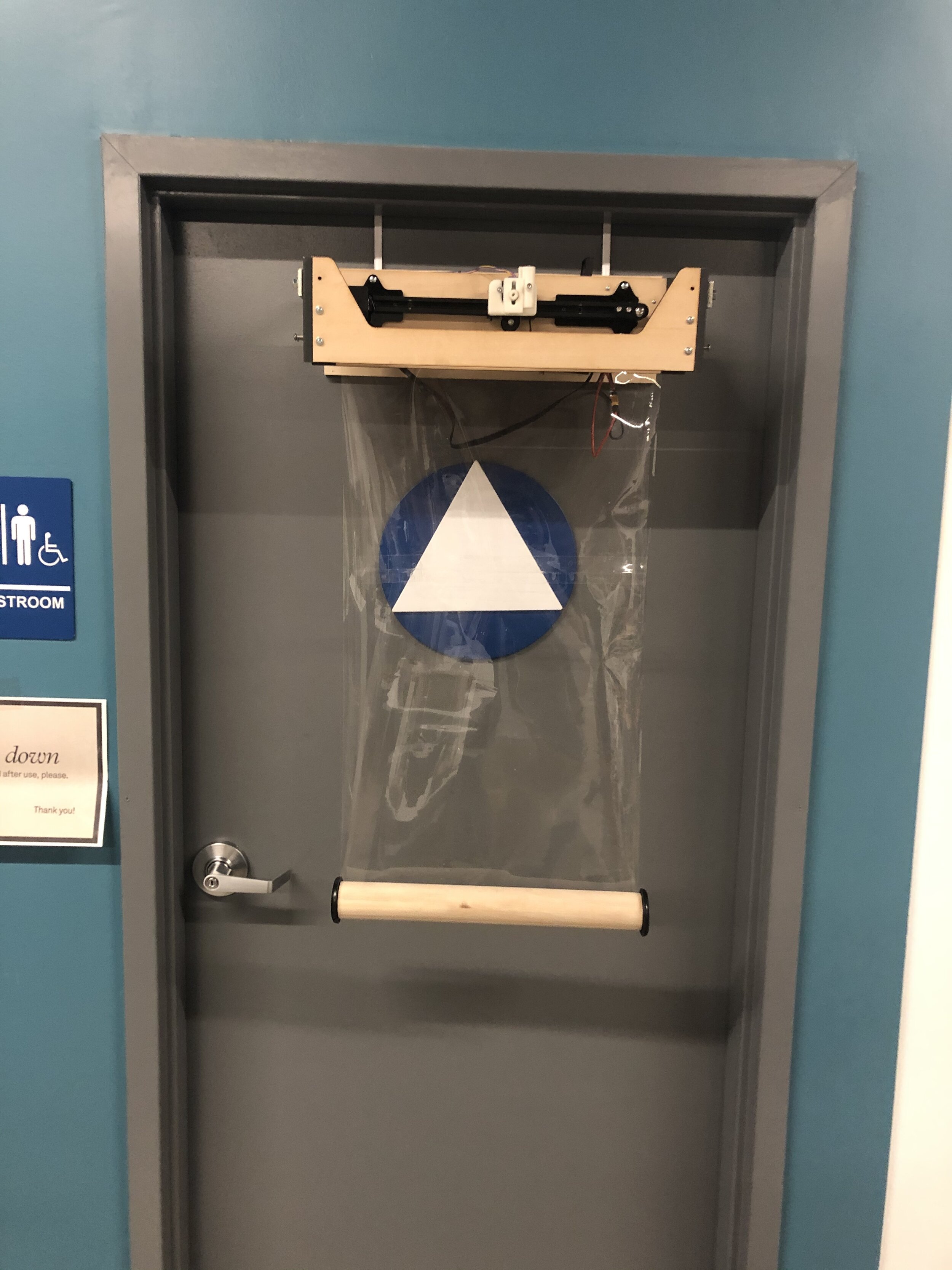
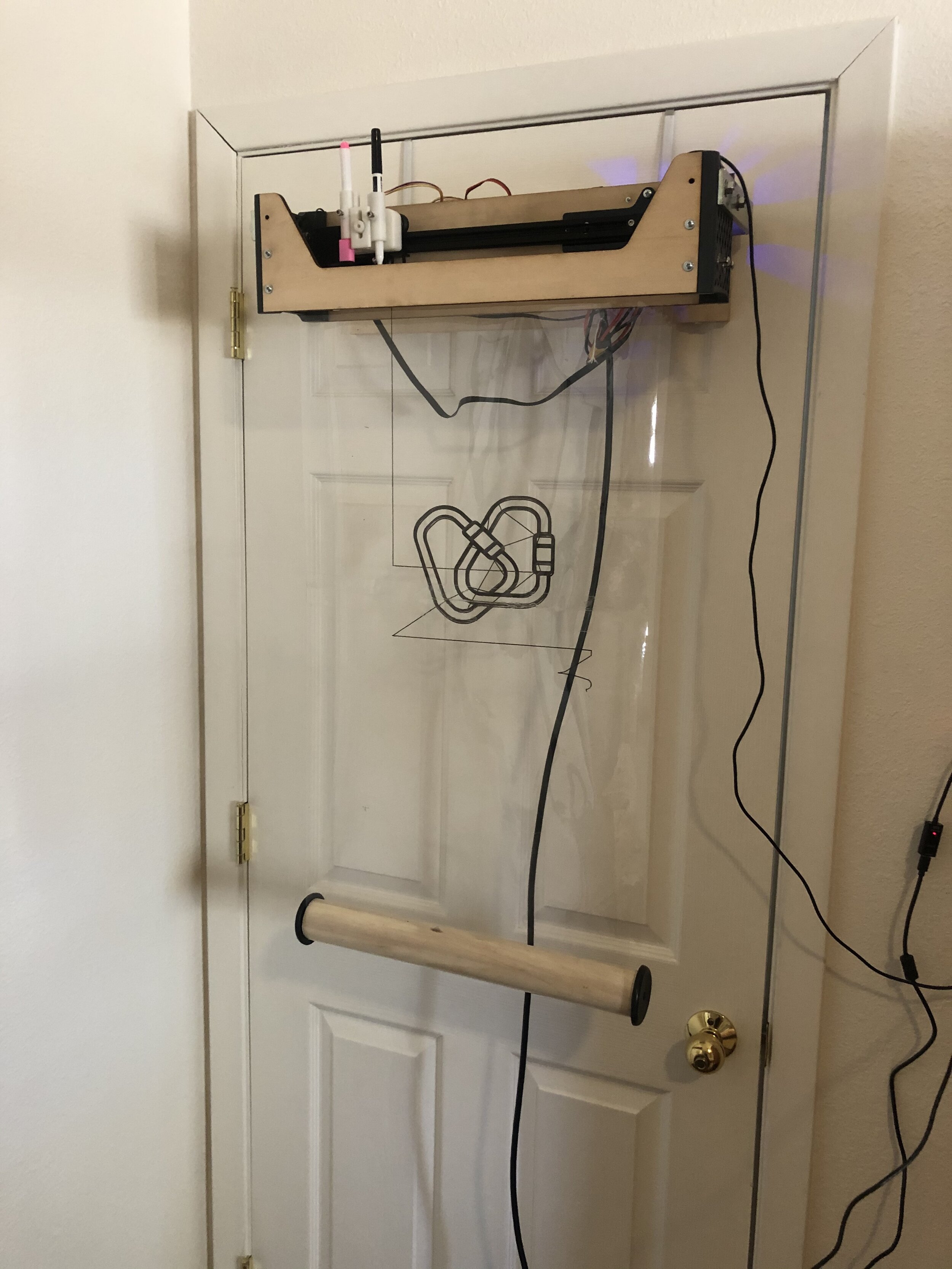
The root of my new approach revolves around the use of a loop of clear plastic as the medium on which the device is drawing. The X axis consists of an independent rail that drives back and forth along the roll of plastic and the Y Axis actually moves the roll of plastic up and down, with the lower end held taut by a suspended counterweight. This affords us a couple benefits that a traditional XY gantry system suffers from. Because the motion of the Y Axis is only moving the mass of the plastic sheet, instead of a gantry, it can drive faster and with small motors. The loop of plastic would be suspended on two friction rollers with a counterweight on the lower end, which would be just enough to keep the plastic tight, but allowed some compliance in the pen mechanism when drawing between the rollers. This layout also allow for a pretty wide range of sizes of canvases with almost no unused space.

MOCK-UP
I started with a mock up of the device to get a sense for the spatial relationships of the rollers with respect to the rail and carriage. It was a wooden test bed that allowed me to drill new holes and adjust things with hot glue. I got a sense for how far the pen might be extend off the rail and how far apart the roller needed to be to get good compliance. I think it really hit just high enough fidelity to reassure me I was heading in the right direction, without wasting any unnecessarily time or effort when I scrapped it all and rebuilt it in CAD fresh.
INITIAL CAD MODEL
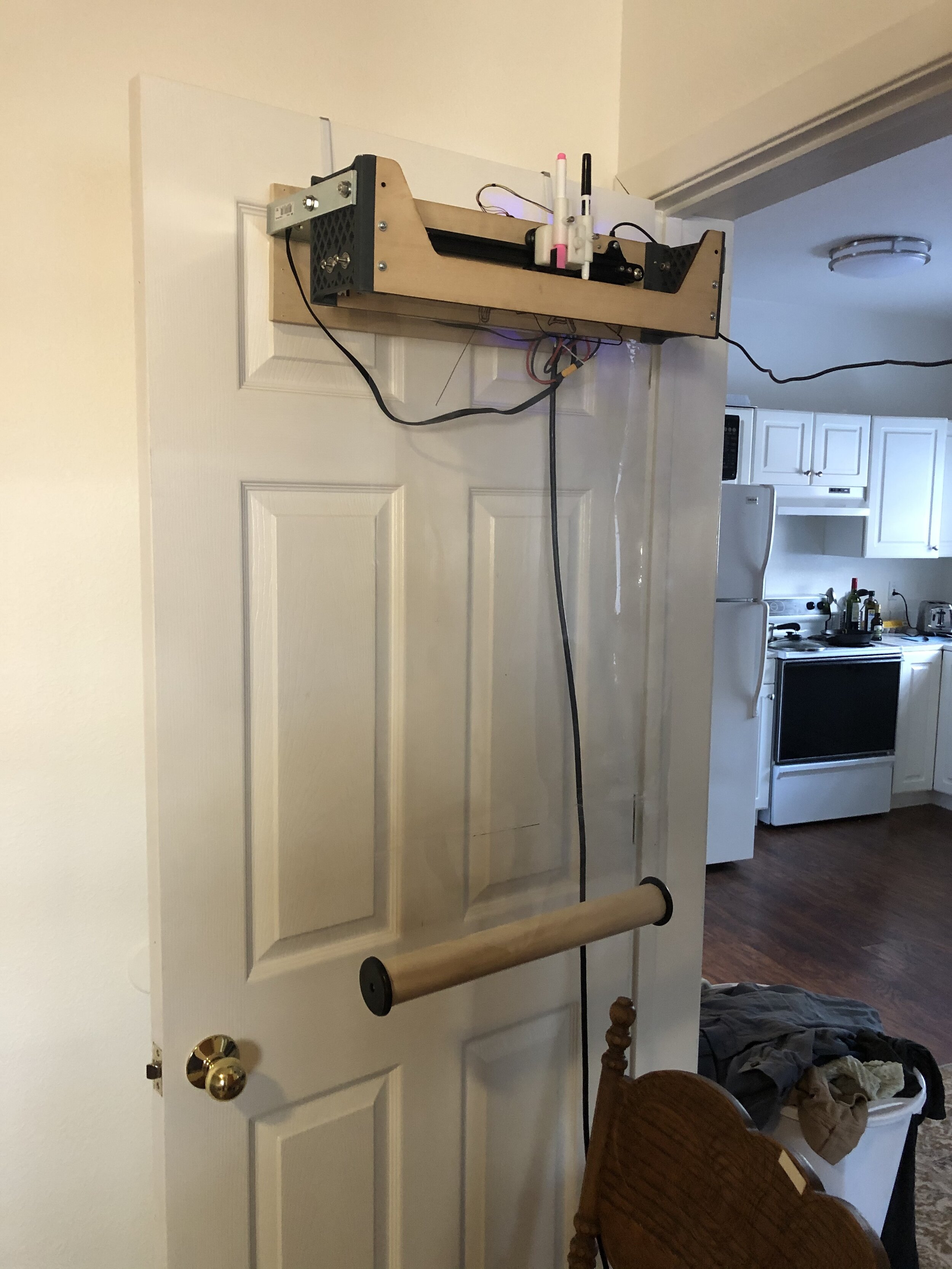
I unfortunately only had about 48 hours of access to the shop in order to build my prototype so my CAD modelling with fast and not terribly well done. It was not driven with a proper top down model and unfortunately, because I was recycling so many parts, I had to try to dimension out a couple elements with calipers that ultimately resulted in a fair amount of imprecision. Much of the electronics are simply placeholders, and since I was on such a short timeline to design it for the small window I had, I don’t think the design did a great job capturing everything holistically and overlooked how I would mount it. I later remedied this with some hardware store brackets that allowed me to hang it on the back of a door.

X-Y PLOTTER
The MVP that I was targeting was a simple XY plotter that only allowed continuous lines. My mockup was enough to encourage me that it might just be possible and as soon as I had the prototype built and the electronics hooked up, it actually came together with very few adjustments. The compliance in the plastic was more than sufficient, though something was causing some bowing in the plastic, and it actually allowed from a pretty big tolerance in the alignment of the X Axis rail with the rollers.
Z AXIS
The first prototype focused testing the ability to draw in the XY plane on the roll of plastic, but it dragged the pen between sections that it intended to draw, which resulted in a bunch or erroneous lines. The output was enough to validate that the setup was going to work, but I still needed to design the pen lifting mechanism to pull the stylus off the plastic. For this I used a simple rack and pinion that drove two holders up and down. This allowed me to put an eraser in one and a pen in the other. Or a two different color pens in at the same time. When the Z Axis was at 0mm height, it would be engaged with the surface and when I lifted the pen to 10mm, the eraser would engage with the surface. This was a key feature in allowing me to continue to use the firmware/CAM/Gcode relationship that I had been working with and not incorporate some special command for switching markers.
The material I used was not as lubricious as I would have liked, but I used some sanding and lubricants to get it to moving just fine. In a future iteration I will look to make this interaction more smooth.
I would also say that utilizing the low power, high torque BYJ48 motor definitely was the biggest hiccup of the whole build. They first need to be modified so that they can run as a Bipolar stepper instead of a Unipolar one, which requires you to cut a trace on the PCB inside the motor. I then struggled a bit to figure out the right wiring for the motor as the first couple times led to some pretty rapid heating of the motor. Fortunately, I figured out the proper wiring before roasting the stepper drivers or letting out any magic smoke.
SOFTWARE
My initial workflow for turning graphics to GCode was about as clunky as it gets. I would take a vector file from something like Noun Project. I would open it in Illustrator and export it as a DXF. This DXF would then be imported into Solidworks and used as the basis of a sketch that would be extruded as a very thin solid (the thickness of a single FDM layer). This was exported as an STL and brought into a slicer called Simplify3D that sliced it, created toolpaths and then GCode to essentially print it as a very thin print that ignored any extruder commands.
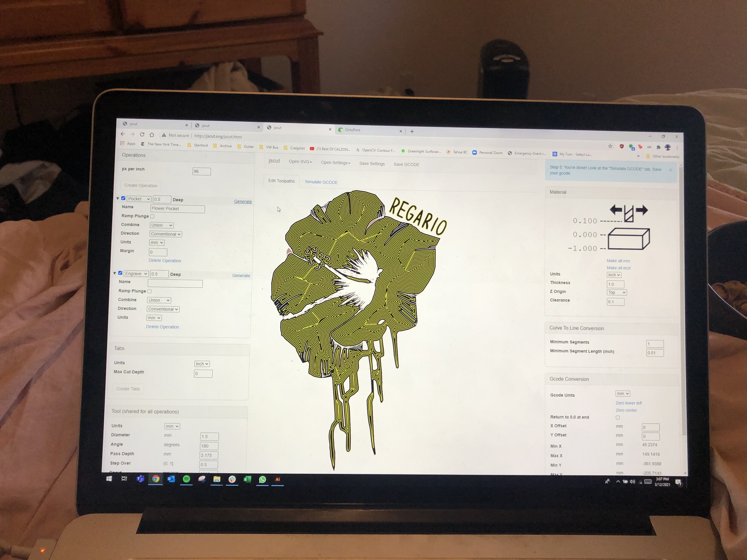
It was obvious that there had to be a better way, which is when I discovered JSCut, an open-sourced web based 2.5D CAM program that converts SVG files to GCode. The user uploads an SVG, selects the regions that it wants to engrave or pocket, selects the width of the tool and depth of cut and then exports GCode for these operations. It matches the needs of my device perfectly and best of it, it is open sourced so I can use it as the basis for a custom platform for interacting with this device.
Graphics part of a collaboration with Olga Saadi.
The other very nice tool I uncovered is called OctoPrint which is a custom RPi image that converts a Raspberry Pi into a middleman for IP/TCP to Serial communication with a CNC device. They have a web interface that allows you to send commands and full GCode programs over a local network to your “3D printer”. This is particularly nice for my application because it means that I don’t need to be sitting pressed up again the wall to run jobs and my computer doesn’t need to be plugged in or even connected while the machine is running.
After some digging, one of the other fortunately elements to fall into my lab was the fact that the Ender3 driver board was actually running a version of the Marlin open-source 3D Printer software. This meant that I could build a custom configuration for my setup and make modifications to the firmware. I had to first burn a bootloader onto the board utilizing an Arduino as an ISP which then allowed me to compile and upload new firmware to my board via the serial connection.
Once I was able to easily make changes to the firmware, there were a couple custom parameters I wanted to change. Primarily, the side of the bed used for soft limits so that I could extend my drawing area. I intend to also eliminate the Temperature control features for both the nozzle and heated bed. I also had to flip the orientation of the Y Axis motor which could be done in firmware instead of rewiring the motor or flipping it’s orientation mechanically.
Eventually I will be moving to some custom software interface that allows the user to easily create, process and print from one place as well as import custom graphics and images from other places.
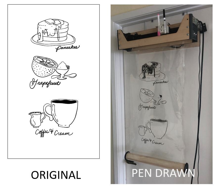
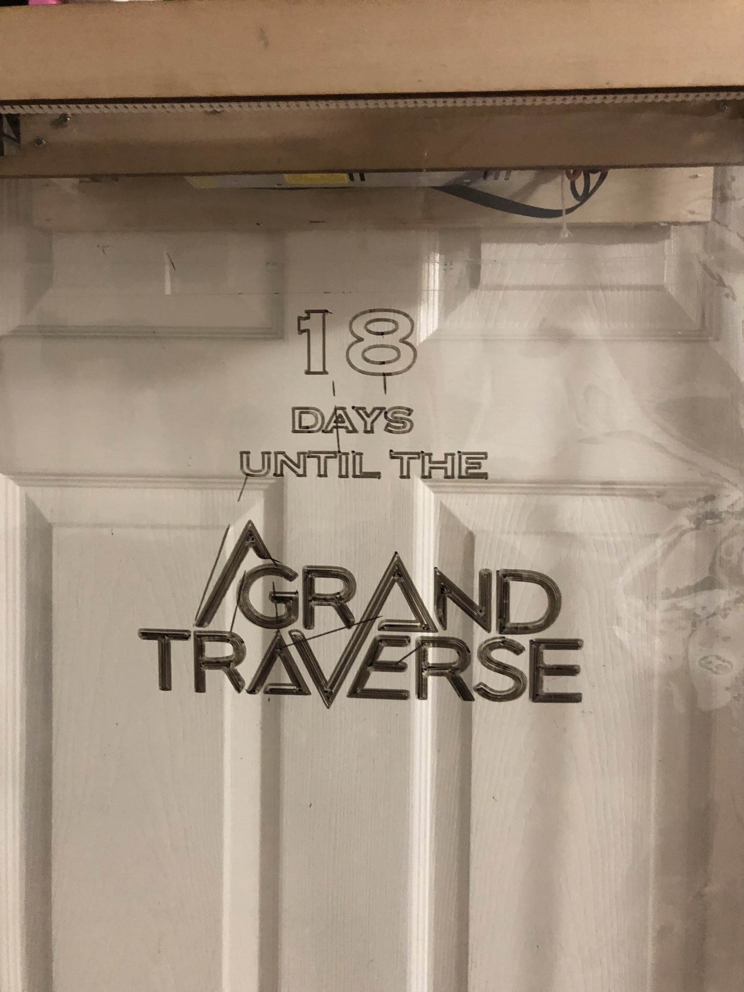
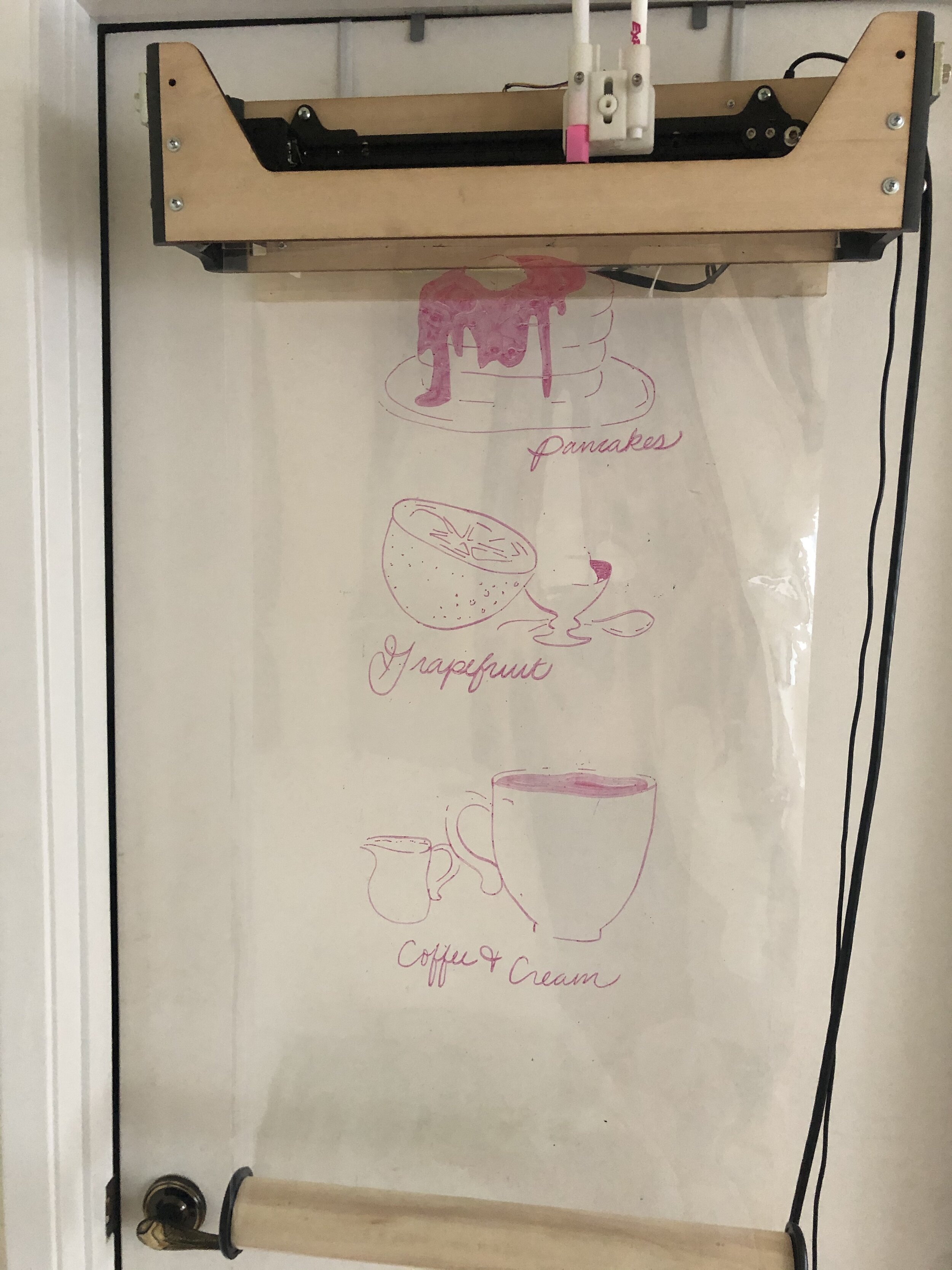
MULTICOLOR
Though the process of swapping pens is not automated yet, I started messing around with multiple colors in a single drawing. The only really technical challenge here is understanding how to properly calibrate each pen between drawings but the insertion process of a pen allows you to pretty easily just drop in a marker. Though I like the idea that the Y Axis could continue on in a one way loop forever, I think I may explore adding limit switches to the Y and Z axes as well so that you can be more confident that the pen is going to the right place every time without the user monitoring or even understanding what is happening.

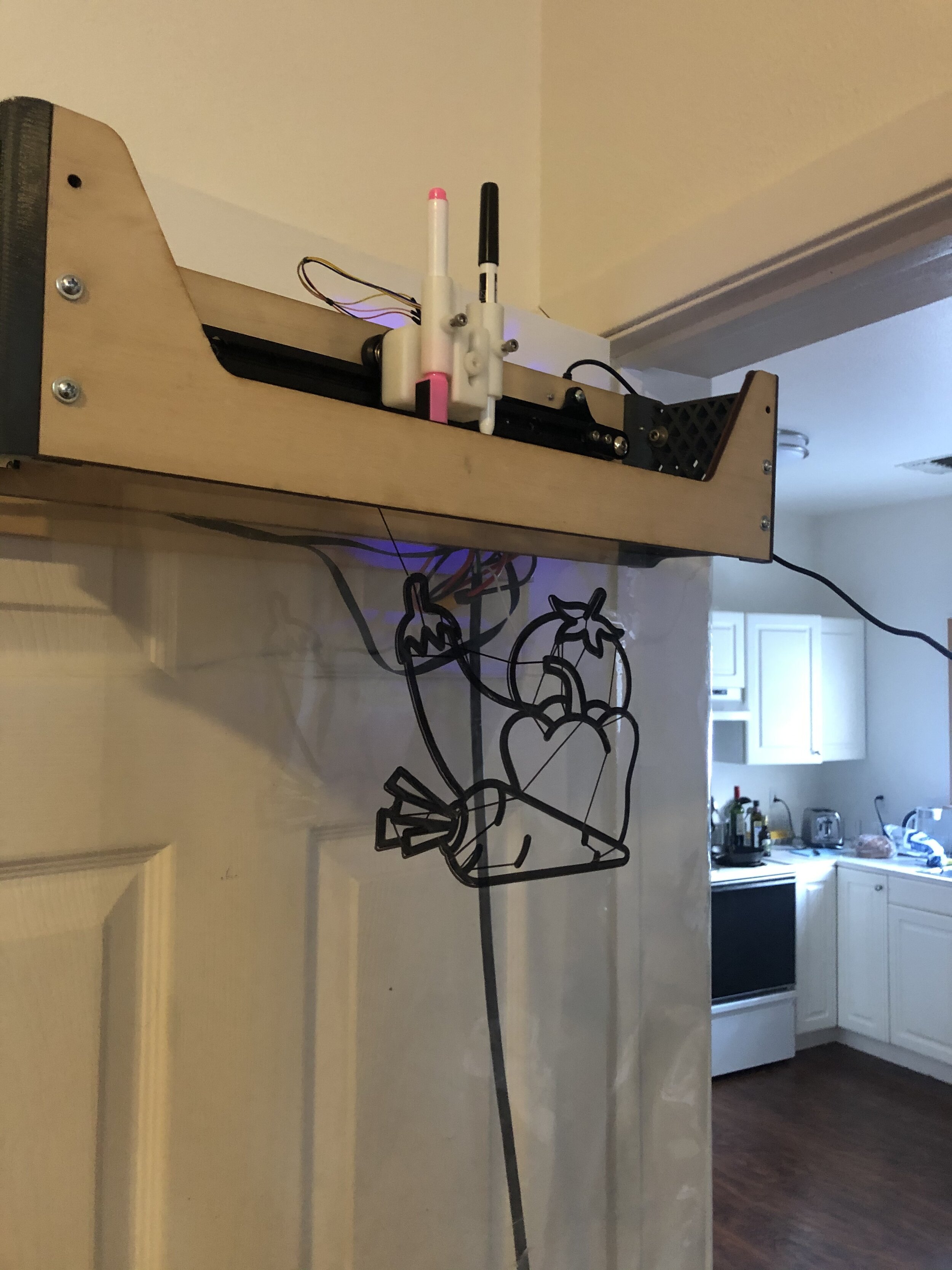
OTHER DRAWINGS //
Here are a collection of other test drawings I have worked with thus far to test out various elements from thin, small features, to different pen sizes to large filled in area.

WHAT’S NEXT? //
Now that the hardware is functional, there are a couple directions I would like to take this to continue to push it forward:
User Research - My hope is that this is a good piece of stimuli to start talking with people and understanding how they might interact with a device like this. I am certainly open to pivoting completely if I have missed the mark, but I think this early prototype could make for a good prompt for discussing how a tool like this could be useful to a small business.
GUI Design & Development - Most likely using the JSCut software as my basis, I would like to start streamlining the process of making and printing graphics so that it is accessible to really anyone. Ideally, the ability to create, process and print graphics would be integrated into one software program that would allows a store employee to update a sign with little know how. I have a lot of learning to do about how a user would ideally use a device like this.
Test the Limits - I believe the only real hardware flaw right now is the lack of limit switches (The Z Axis could probably use a rebuild too…). I would like to try to integrate an optical encoder to find a zero position on the Y axis and the Z Axis could probably use a feature on the pen carriage.
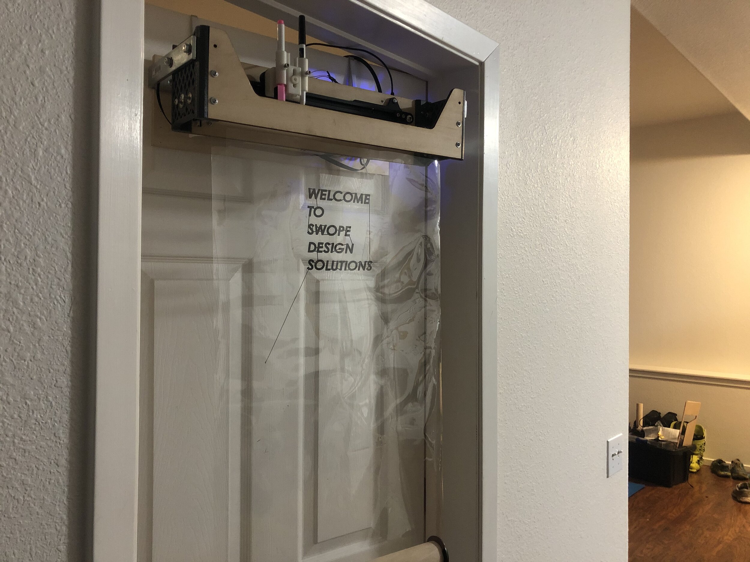
Aesthetic redesign - One of the learnings about the design of this prototype was that when it is suspended at the top of a door, the drawing process is a bit hidden. The interaction between the pen and the plastic is something that I really want to showcase and highlight, so I think in a redesign, I would figure out how to accent this more.