
OBJECTIVE // To design, prototype and ultimately injection mold a clamp that could be used for filling seed pot bags for farmers working with Kijani Forestry in N. Uganda. The clamp will hold the bags in place while soil is inserted then release them after packed completely. Utilizing the HAAS CNC mills and the 55 ton Injection Molding Press in the Product Realization Lab, my goal was to machine soft tools in aluminum and shoot plastic parts to be sent to Uganda for testing at scale.
BACKGROUND // As part of the Design for Extreme Affordability program, three students and myself partnered with an organization called Kijani Forestry who focuses on combatting the deforestation in Uganda by working with farmers to plant trees on their land to be more sustainable harvested for charcoal production, Ugandan’s primary cooking fuel.
Though our intended travel to conduct our in-country research was cancelled due to COVID, we were able to conduct some interviews remotely and ultimately focused on paint points for the farmers during the bag packing process. The farmers pack these small plastic bags, the size of a soda can, with soil and a seed, which is then nursed for a few months before distributed to be planted on the farmers land. It was clear that the difficult part of this process was holding the bag open during the first handful of soil so we focused on this step.
After exploring a couple different options, we landed on a plastic clamp that would squeeze onto the bag and allow the user to funnel soil into it, then release the bag once it had been filled. We built a prototype (with the very COVID limited resources that we had) and got it into Kijani’s hands to test.
DESIGN FEATURES & IN-COUNTRY TESTING //
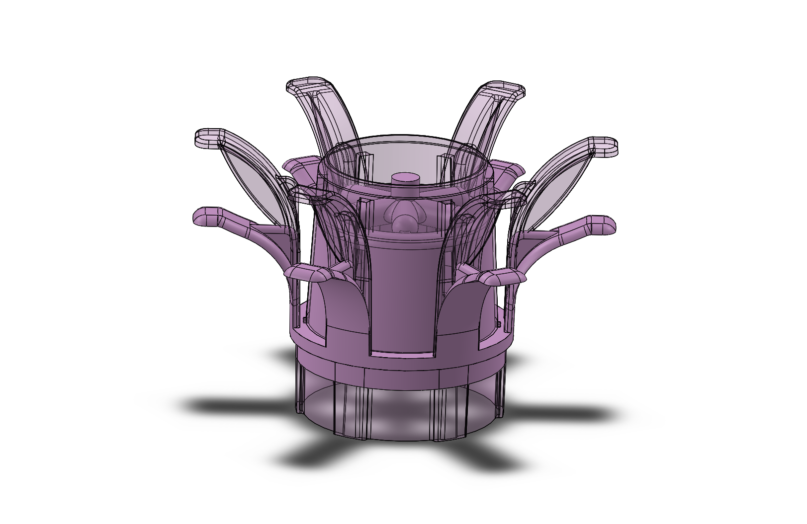
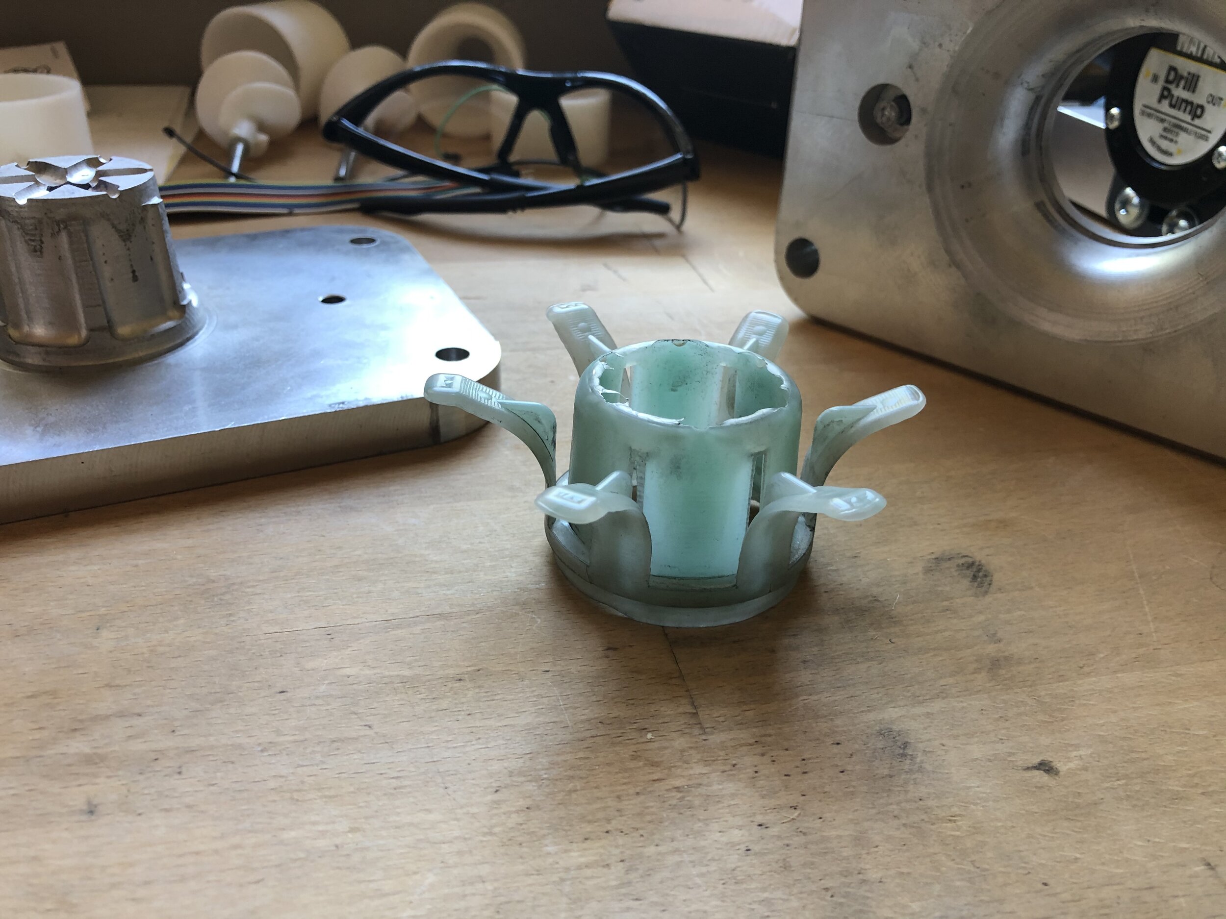
The clamp consists of 6 spring fingers that are depressed by the inner diameter of a hole cut into a piece of wood. As the two boards are separated, the fingers are driven into the cone, creating a pinching action on the bag material and locking it in place. When the boards are pushed back together, the fingers are unloaded and the bags of soil drop out of the clamp.
Since we released the design and initial prototype to Beau and the Kijani team, they connected with the local makerspace Oysters and Pearls to keep developing the design as they test it. Despite our restricted our access to prototyping tools were, they were able to continue to advance the design using FDM 3d printing.
Unfortunately, if Kijani is going to plant millions of trees, they are going to need a lot of clamps, which means that they would need a lot of machines running for a long time to get enough. The hope is to harness what they have learned in their prototyping to design an injection moldable component, machine the aluminum molds, and shoot polypropylene parts that we can send to Kijani to test.
Below is a video showing the work the Beau and Elias, from Oysters and Pearls, have been testing and revising.
Though the design had evolved a couple iterations while in Uganda, the work was also dependent on the part being 3D printed, which has its own particular constraints, so when I started looking at how I would injection mold it, there were some clear things that needed to be changed. Since I was also machining the molds myself out of aluminum, on a 3 axis CNC mill, there were also going to be limitation on certain things such as how deep I could machine into the mold, which affects the height of the part.
When I started getting into the details, it appeared as though I was going to have to make the overall height shorter to fit the mold. This meant that the thickness of the plates will need to be 0.25” instead of 0.75”, which could present a sourcing issue down the line and is still unclear whether it causes an issue from a strength perspective. I also needed to eliminate some small features and increase the small deep features to a minimum diameter of 0.125”-0.25”.
Elias and Beau had added a rib to the exterior of each of the fingers, but after testing it a bit, I didn’t find I needed this rib and since it is a tool safe addition, I figured I would omit it initially and add it in if needed. As a consequence of the geometry of the press, I was limited in the aluminum mold height to 2.75” which meant I needed to shorten the part in order to fit it in the mold. In principle, this would likely be ok, but it would mean that the fingers were shorter than before while deflecting the same amount, which would cause increase stresses.
DESIGN FOR INJECTION MOLDING //
The first step was making a design that followed the basic injection molding principles: even wall thickness and fully drafted with at least 1 degree of draft everywhere. Making this work, while also keeping an eye on machinability of features meant examining each design decision from multiple different lenses at once. Each change to improve the design would likely have moldability concerns which also then had machinability considerations.
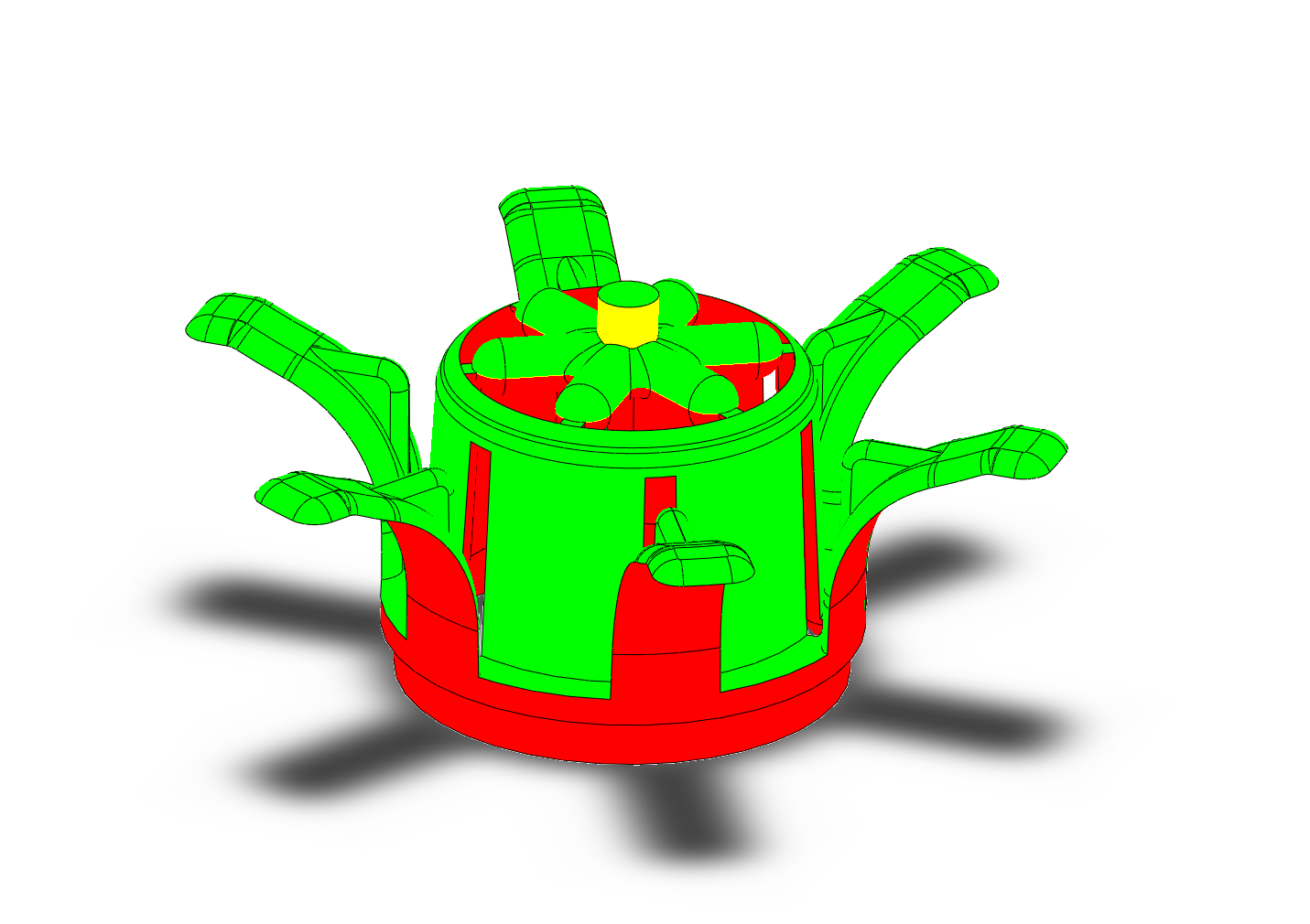
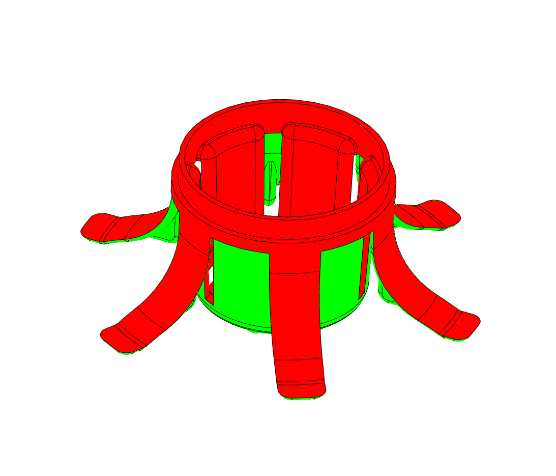
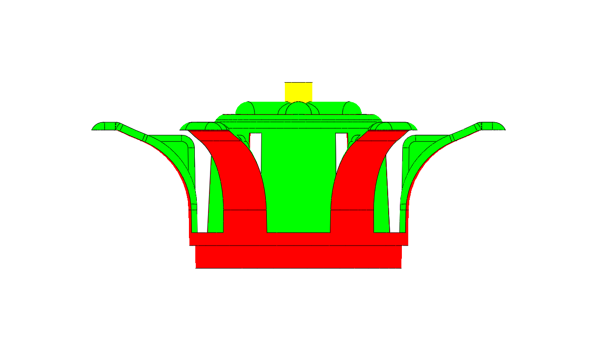
The color breaks here show the direction of the draft and where the parting line was going to be. Because it was essential that the fingers substantially overlapped with the center post, I needed a passing core to create these slots. This meant that the A and B sides of the mold shutoff on one another inside the part, which would be quite challenging. Without a good shutoff, the plastic might web across the opening preventing the overlap of the fingers and core.
FLOW SIMULATION //
After I had all of the basics settled, I needed to consider how I was going to actually mold this part. With the symmetry, it makes the most sense to gate right into the center in order to get an even distribution of plastic. I used 6 gates/runners to match the number of fingers in an attempt to make things as even as possible. Though simulation and general intuition, you can see that there will be some knit lines meeting between the fingers. This isn’t hugely problematic for our part since there isn’t a huge cosmetic or function significance to this area so I decided to leave it as is.
After reviewing the mold analysis, it didn’t appear that there were going to be any issues with fill or unreasonable pressures to mold the part so I decided to press forward with the design.
CAM SIMULATION // After deciding that the part was in good shape, it was time to move towards the mold design. I knew from the start that the design of the mold would be a bit tricky in order to get all the geometry that the clamp needed while adhering to the realities of the CNC tools. To accomplish this, I broke the mold into an A, B1 and B2 mold where the B Side was split into two parts. This allowed me to get the deep parts of the tool without having to use very small, long tools.
Above, you can see the simulations of the CAM running demonstrating the steps required to efficiently machine the molds, moving from large shell mills to small tapered ball end mills.

MACHINING // In the interest of speed, I regrettably opted to machine away large sections of aluminum instead of build the molds in two parts. Some of this was unavoidable, and unfortunately, I ended up having to rework the part so much that I ended up breaking it into two parts anyways.
This was the first job I was able to run on the HAAS machines in the PRL so there was lots of learning done all at once. The largest one had to do with the limitations of HSMworks, the CAM software I used. My early operations for each of the parts involved using the shell mill to carve out some large sections of material. When I started doing this operation, the machine started to rumble like there was an earthquake. Upon further inspection, there were sections of the aluminum that looked that they were smeared out of the way rather than cut. What I realized shortly after was that the shell mill, which is non-center cutting, was plunging inside of the part and forcing material out of the way instead of cutting it.
I went through my CAM again and made sure to tick the “Plunge outside of stock” was ticked. Unfortunately, despite this, the toolpath was still plunging inside the material causing the same noise. After a lot of discussion with other TA’s and a bunch of different creative work arounds, I ended up having to manually force the tool to start outside with rather clunky operation.

I wasn’t enormously happy with the surface finish on the first attempt machining which I think was predominately related to the chatter of the tool. I think I was using too long of a tool to make the roughing cuts. I could probably also stand to get some sharper tools as I was using communal lab tools.
FIRST SHOTS // I decided to begin shooting my parts in polypropylene as it was the easiest to flow and fill as well as very flexible which was great for the flexing fingers. Initially, I had a little bit of an issue getting the mold to come together but after a bit of strategic sanding, I got it into a place where the injection press could happily push them together.
For the very first shots, I was having issues with the parts getting stuck in the A Side. Even after coating everything with mold release, I still couldn’t get a part out without disassembling the entire mold, which was certainly less than ideal. Unfortunately, I wasn’t able to use the ejector pins as the set holes didn’t line up with my part. After a lot of brainstorming with Marlo and Craig, we came up with the idea to use the middle plate as a stripper plate where the ejector pins would simple push up the middle plate, releasing the parts.
Of course as soon as I implemented this, the parts started getting stuck in the top of the mold…
ITERATION 2 // Though I eventually got the parts to come out quickly enough, when I went to go test them to see if they would clamp, I realized that some of the shutoffs weren’t clamping as well as I hoped and there was flash bridging over them making it impossible to pinch the bag. The holes also weren’t quick large enough for the pinching nubs to enter into the clamp. Unfortunately, these changes weren’t tool safe and necessitated a reconstruction of the mold into two parts: a core and a plate. I used two dowel pins and two bolts to rigidly attach a block to the plate and despite the less than perfect surface finish, it seemed to work pretty well.


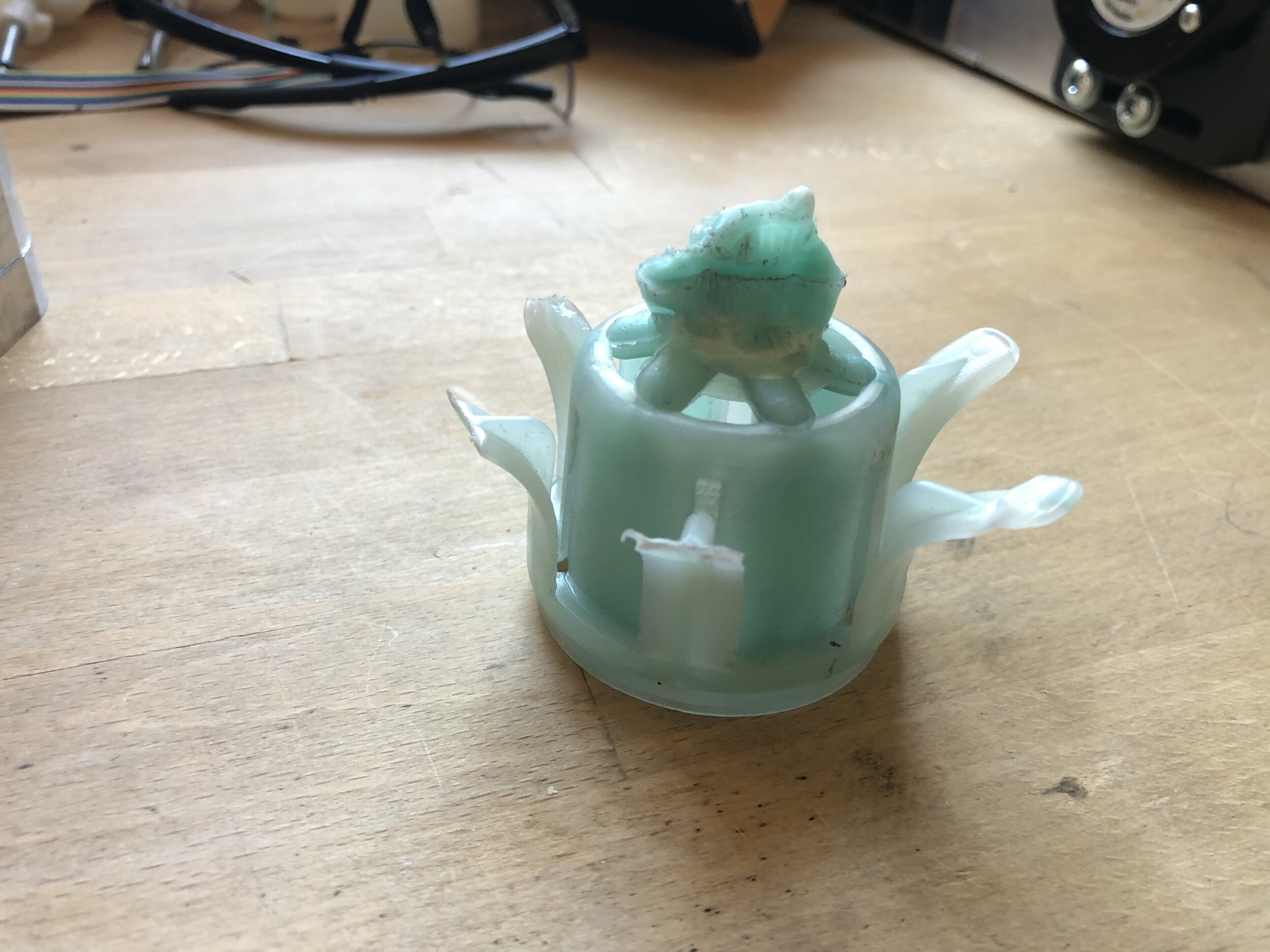
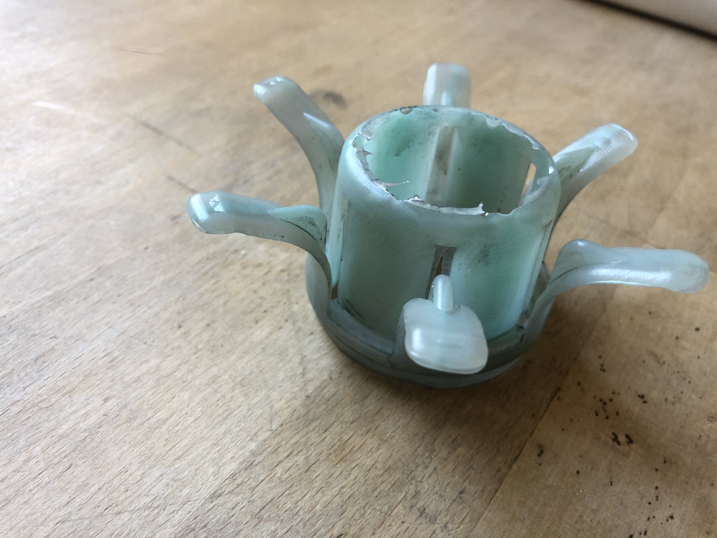
ITERATION 3 // When I reassembled the mold, I was able to get parts out of it without anymore flash which was a big success. Unfortunately, now that I was actually able to test the functionality, there forces to clamp the arms was just way too high. Though I had tested the clamp in SLA before moving to tooling, I foolishly made a last minute change to the part and shortened it significantly not realizing the implication to the rigidity of the fingers (shown below).

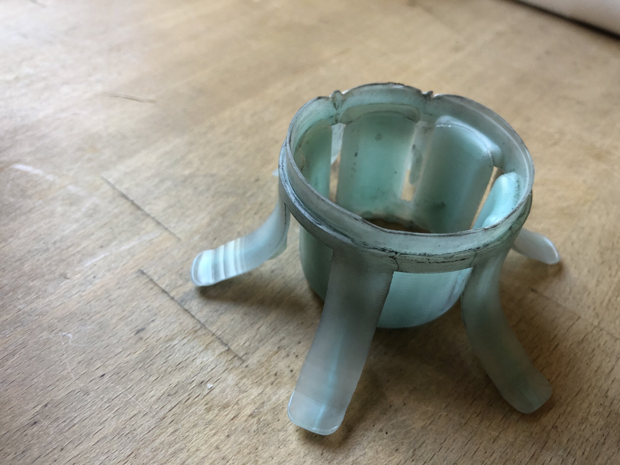
To remedy this, I redesigned the part to be a bit taller with thinner arms so that the deflection is occuring over a longer throw. I tested this again in SLA and I am optimistic that this iteration will remedy these issues. I am in the process of finishing this mold and will update as the design continues.
