The Hangbot
OBJECTIVE // Create a hanging wall plotter that could be suction cupped to any smooth hard surface and used to draw vector art and render images anywhere.
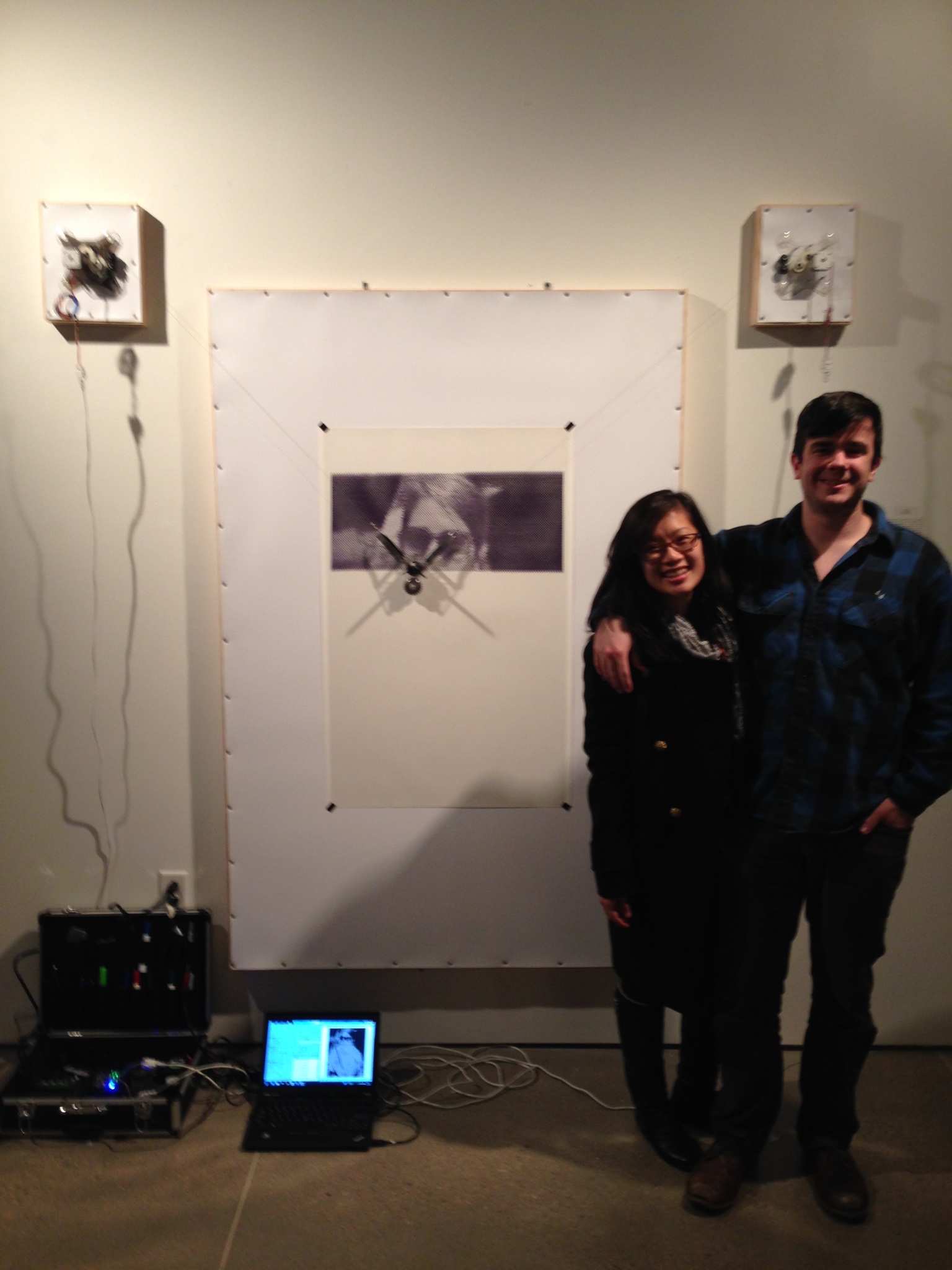
TEAM MEMBERS // Jack Boland and Ian Anderson
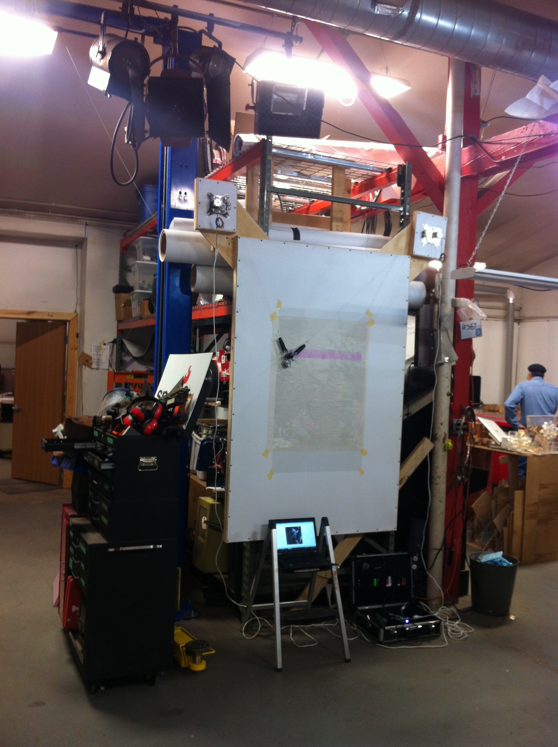
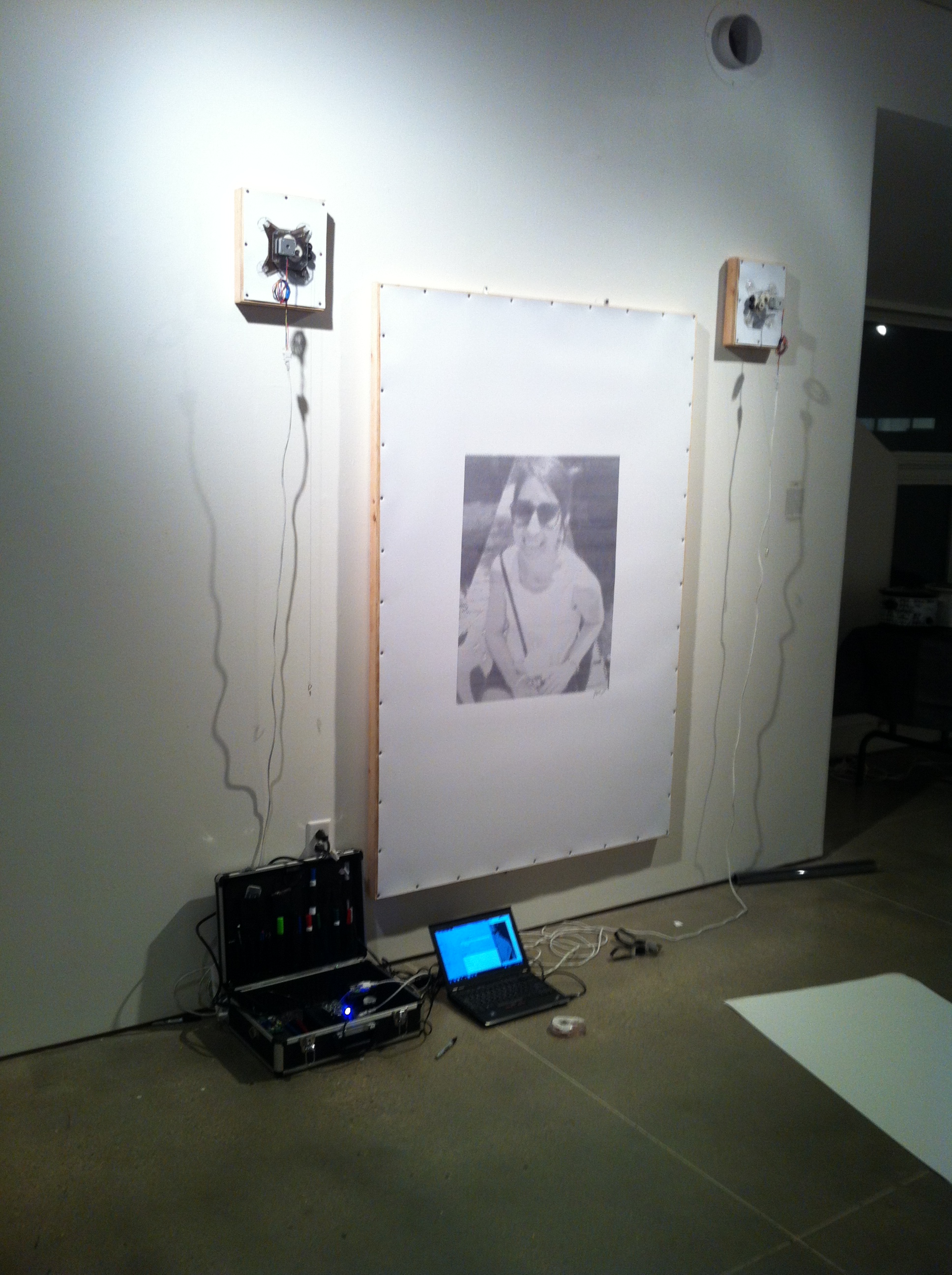
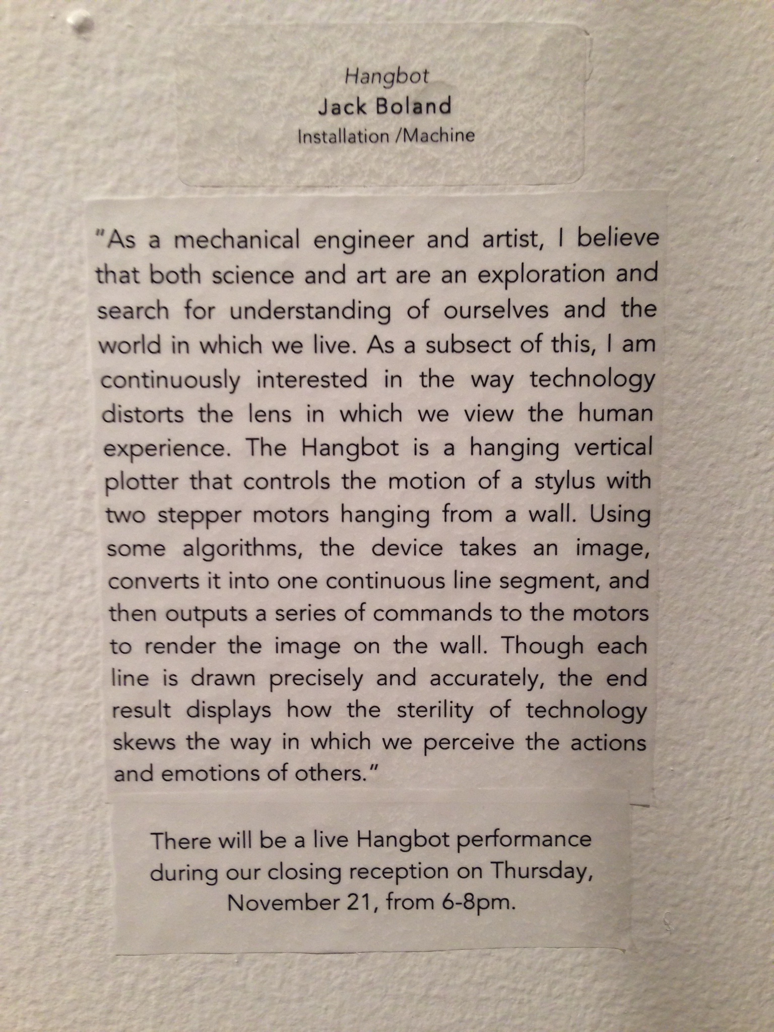
DETAILS // The Hangbot Project was originally the focus of my research, An Exploration of Mechatronic Devices for Physical Displays of Data Streams and Environment Interaction , in the Wisconsin Institute for Discovery during my senior year as an undergraduate. The vertical plotter consists of a stylus hanging from two stepper motors by strings. A microcontroller and motor shield interpret computer commands in a way that renders the image, text or other data on the flat surface that it is mounted.
Joining forces with chemical engineer, Ian Anderson, and MFA candidate, Paul Lorenz, the Hangbot sits in between engineering and art. The team members were each named Frontier Fellows in the WID in early 2013. Here’s the abstract from our proposal:
In this age of paperless records and LCD displays, the days of physical data records and tangible graphics seem to be becoming a thing of the past. With the accelerating pace of technological developments moving quickly from the physical to the virtual, there has been a lack of development of methods integrating both of these sides of data collection and representation. The objective of this project is to develop a device integrating the precision and complexity of computer generated graphics and the intrigue of kinetic sculpture with a physical method of recording and displaying information.
The Device
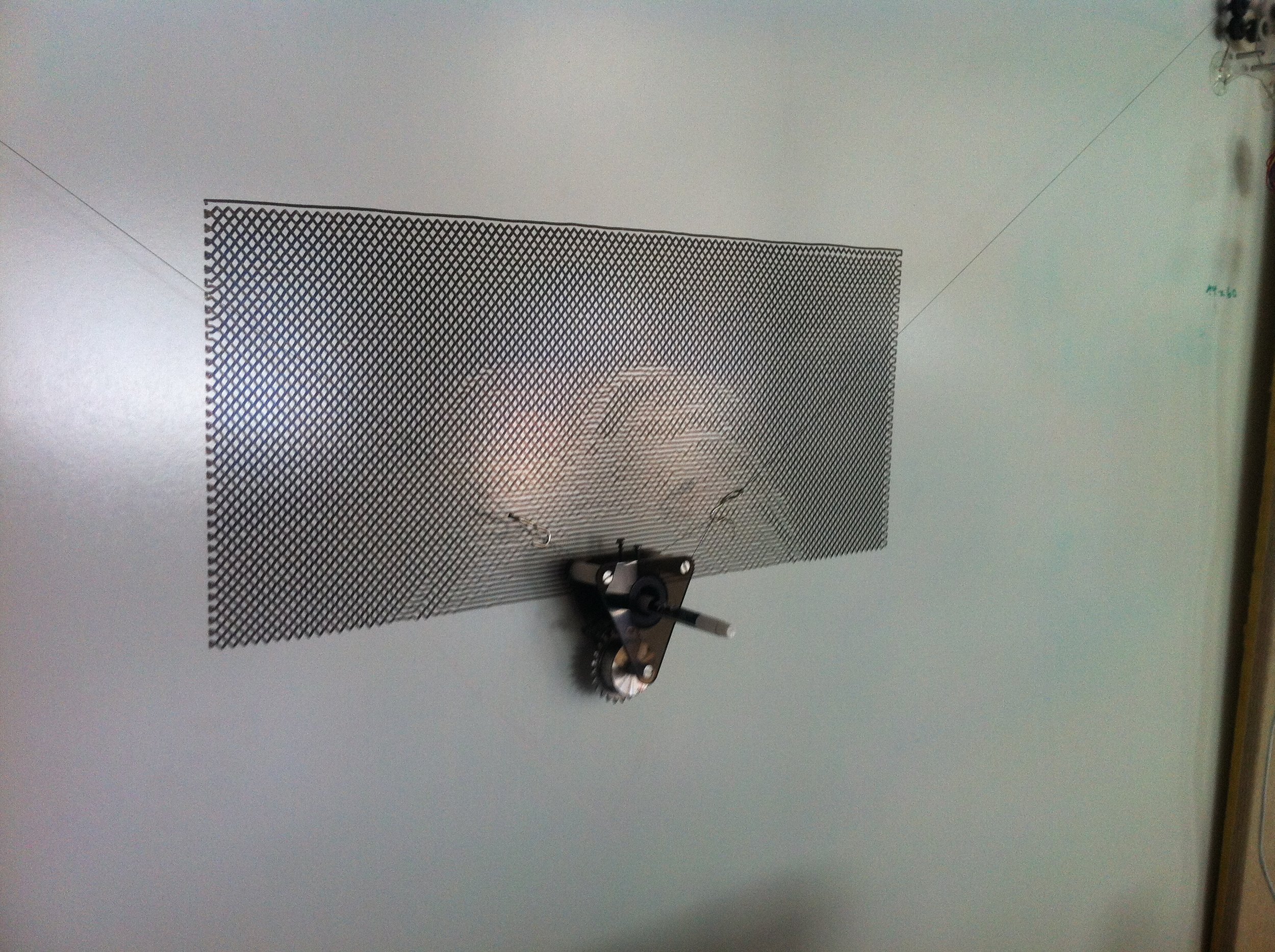
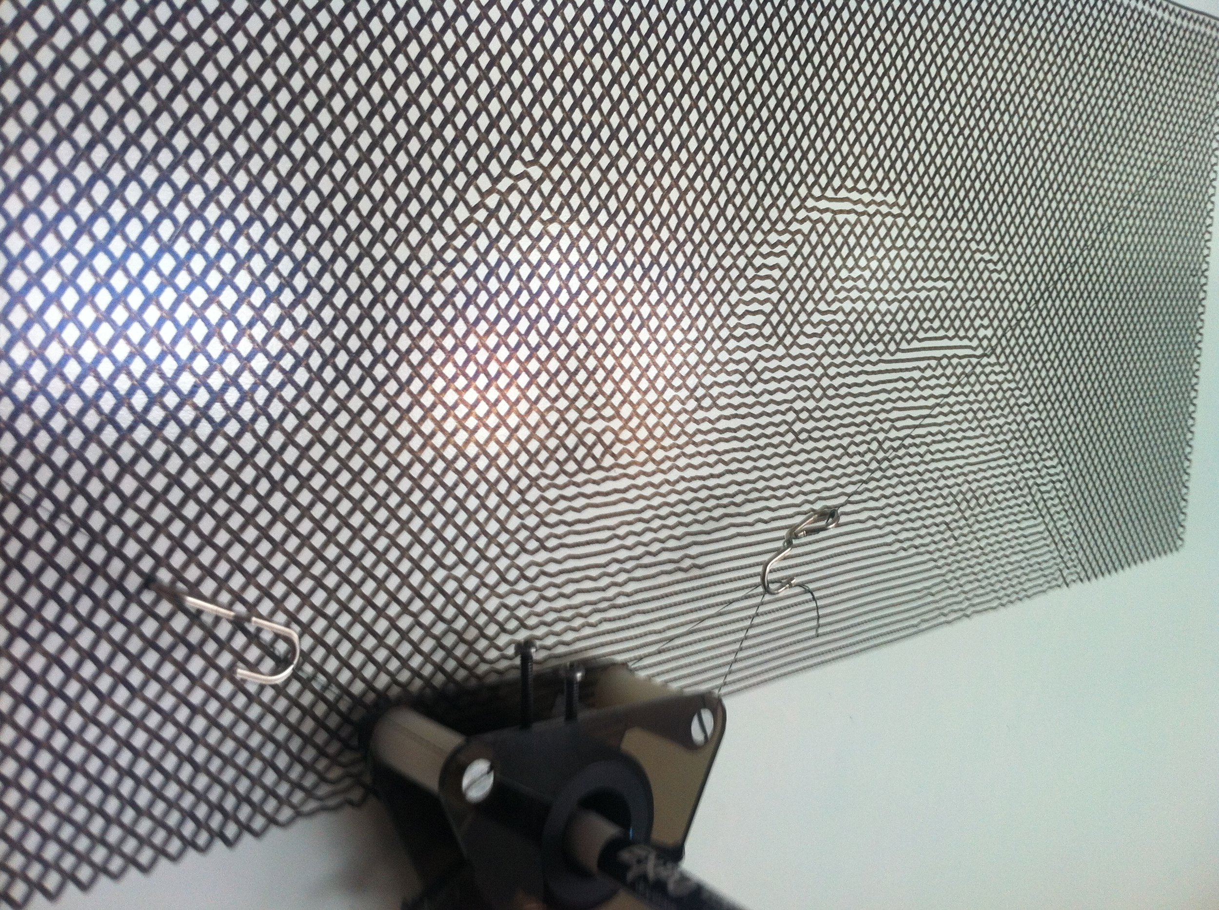
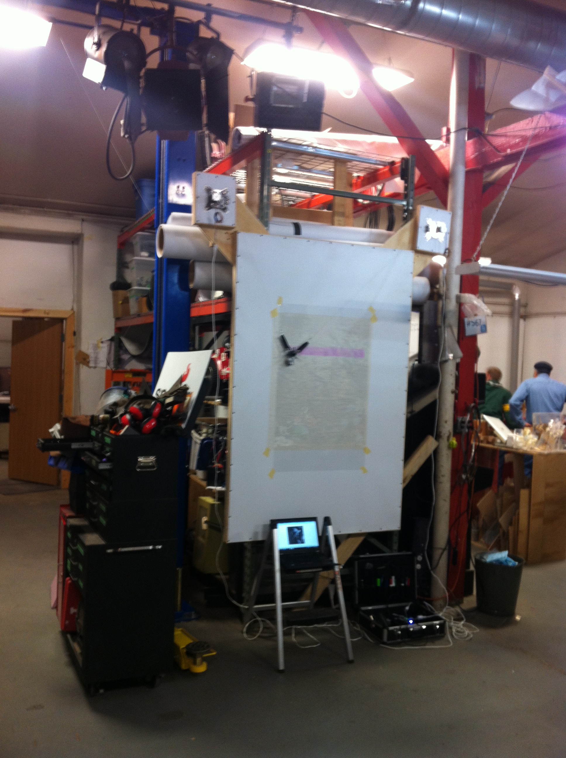
The project originated from a small open source CNC mill that my boss gave me one summer. First, I took apart all the hardware and reused what I could to construct the first version of the anchors. Each anchor consists of some laser cut acrylic panels, a stepper motor, some 3D printed (FDM) gears, and some suction cups. The intent was to allow the anchors to be stuck to any smooth surface for in situ wall drawings.
Each anchor is connected to a motorshield via Ethernet cables and the shield is mounted to an Arduino. I located a copy of the firmware on Githuband started editing it with AVR Studio. Once I implemented the necessary geometry modifications, I used a program called XLoader to flash the new firmware over to the Atmel chip. The modifications were made in a manner that allowed the controller to still function as it was originally intended and accept GCode commands from the ‘Universal GCode Sender’ program that I found online.
Early Drawings
Since the controller was still utilizing GCode, I started producing images using the CAM software CAMBAM. I produced two bit images in Inkscape and converted them into vector graphs to import them in the CAM software as DXF files. Here, I applied a horizontal fill, generated tool paths and GCode to essentially ‘engrave’ the image (zero offset for tool thickness). Then using the Universal GCode Sender I sent the lines of code to the motor controller line by line.
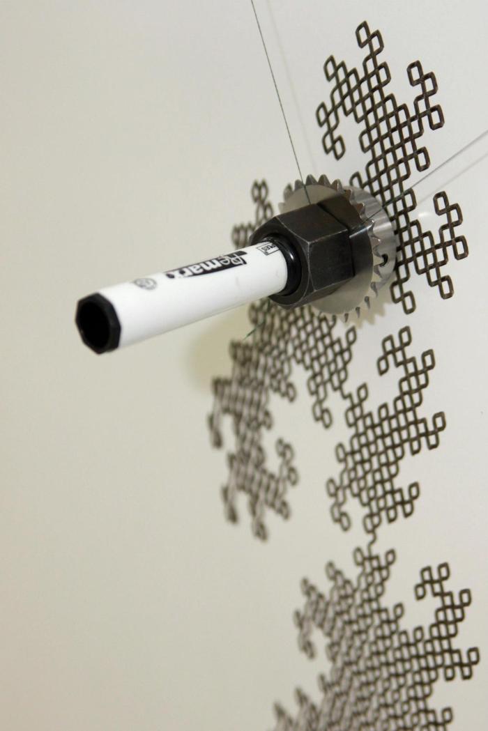
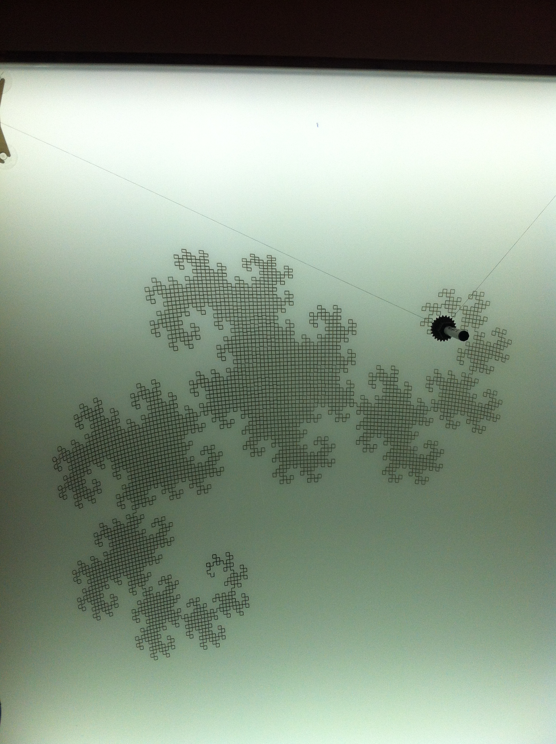
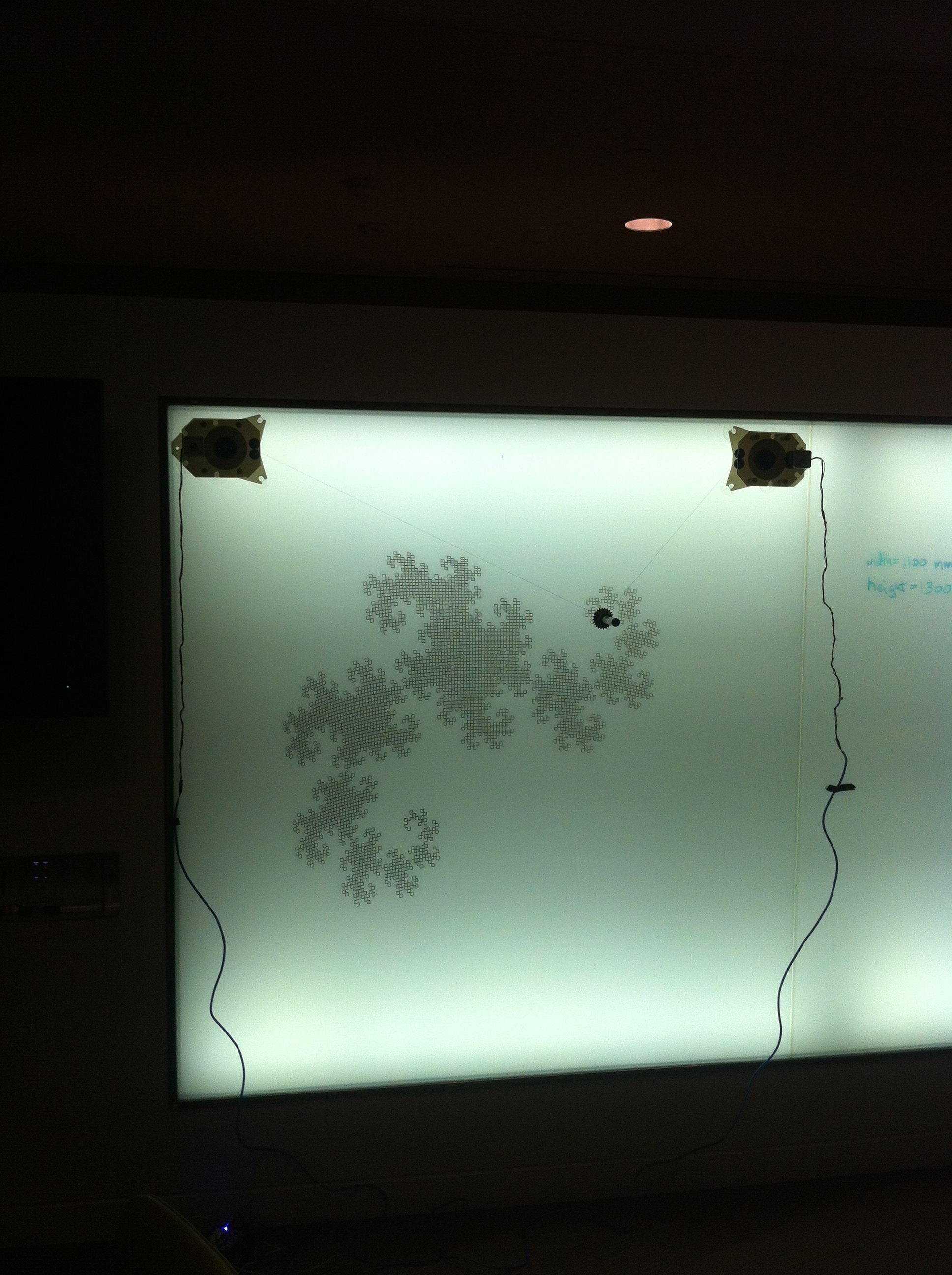
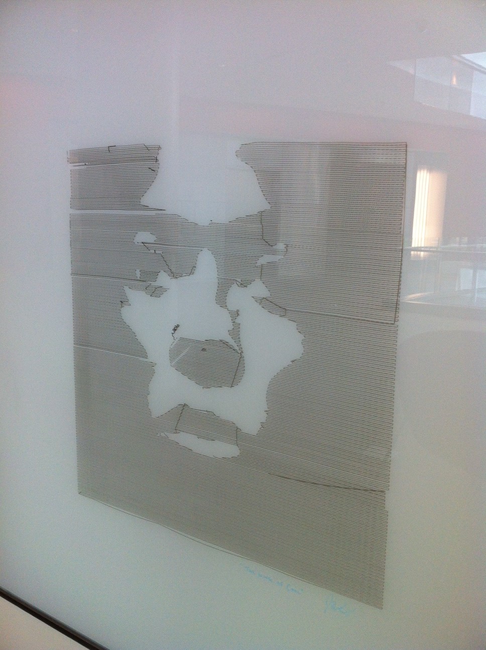
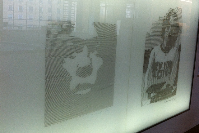
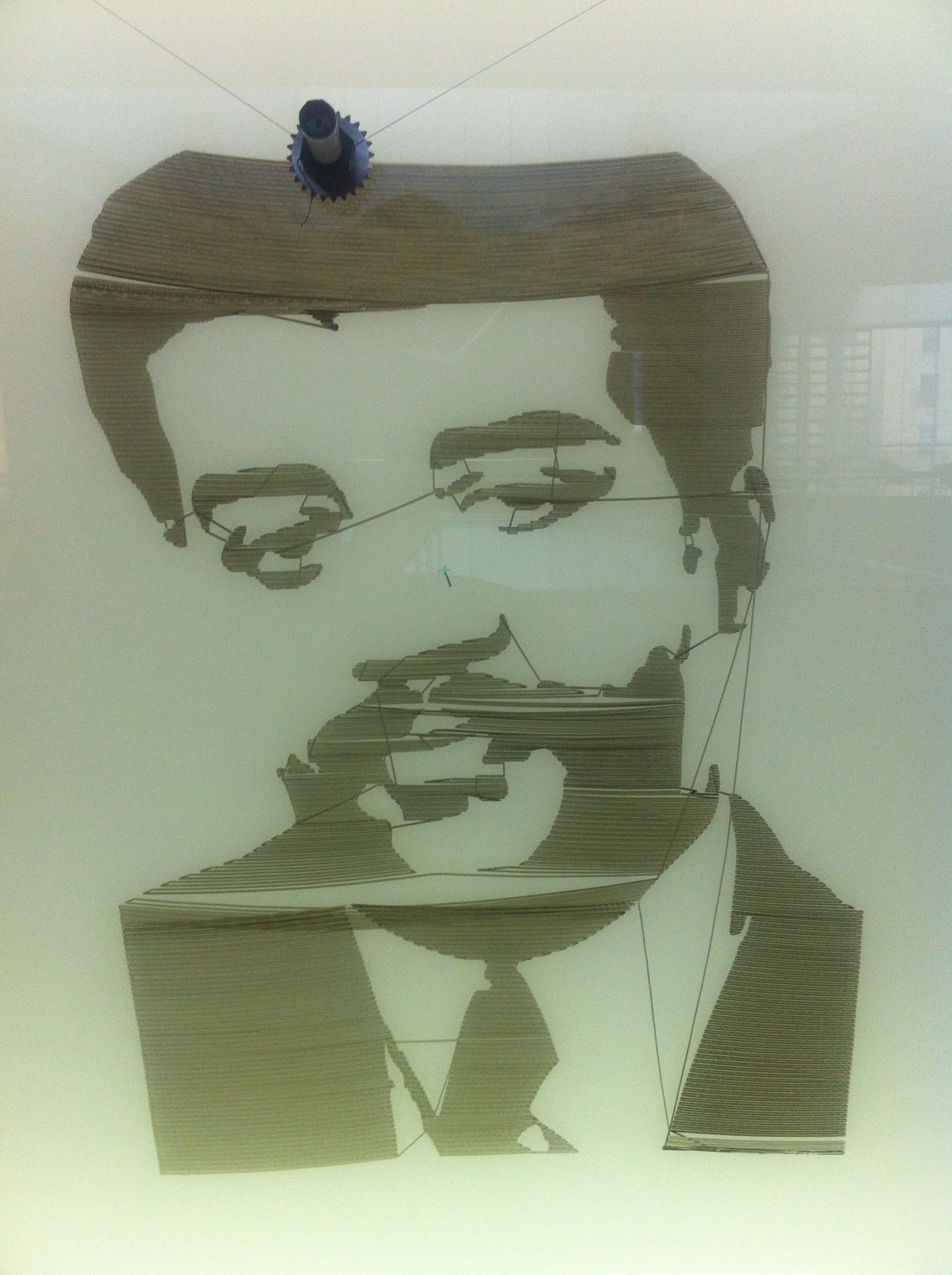
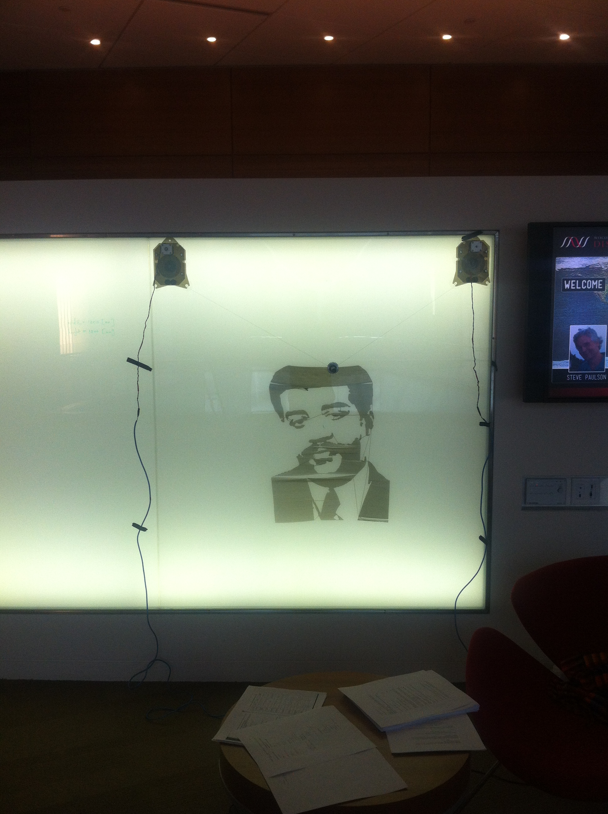
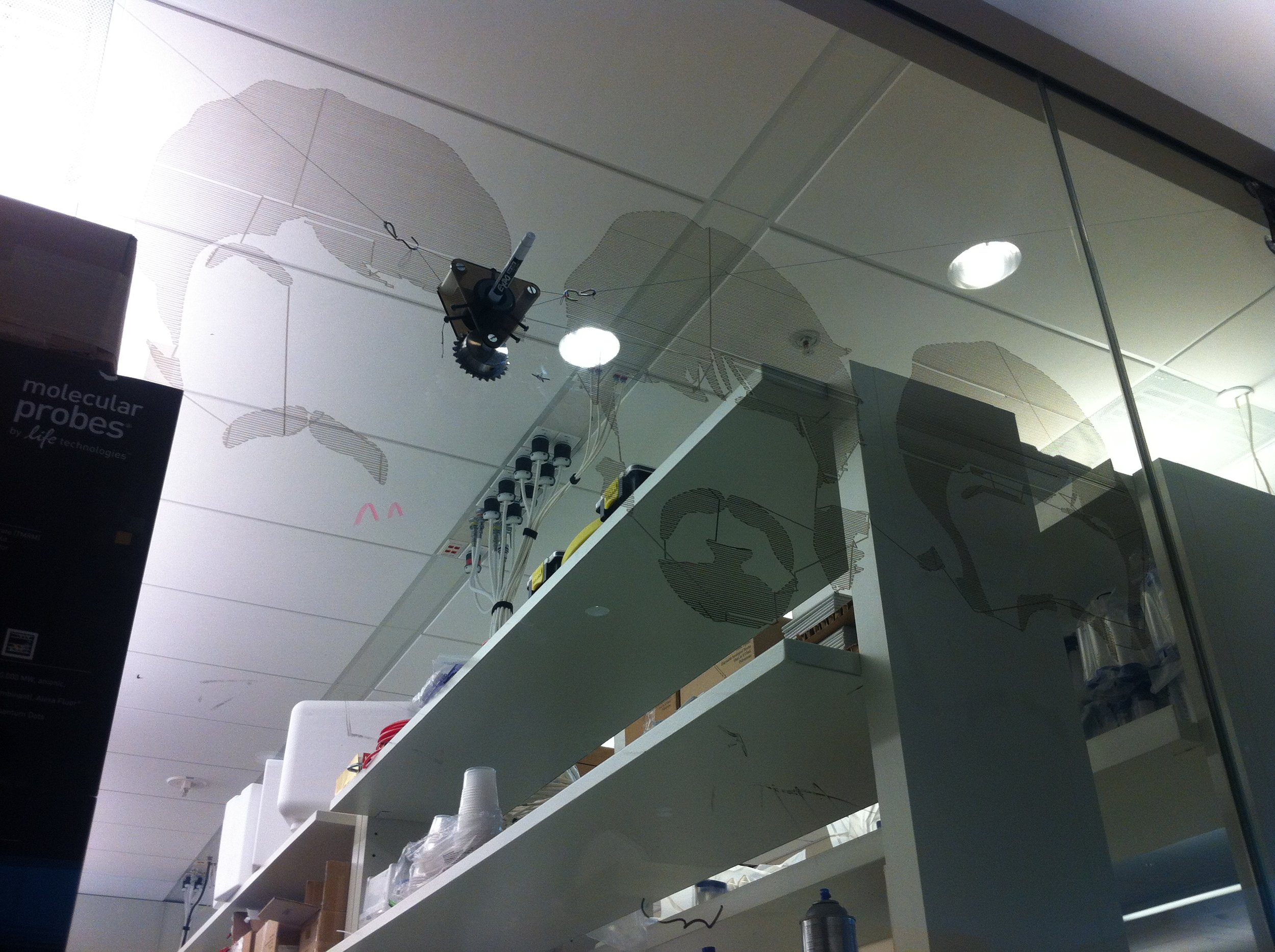
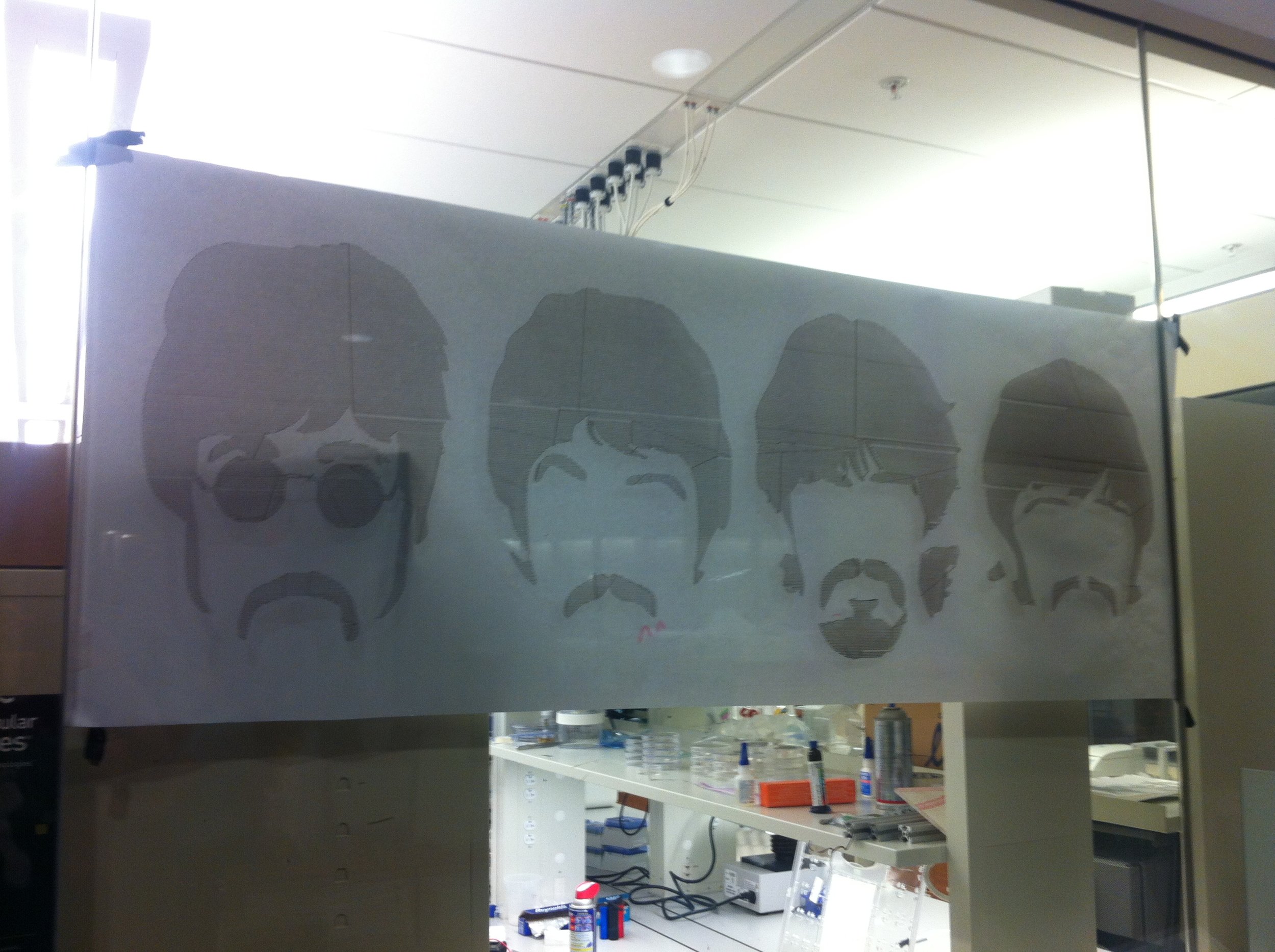
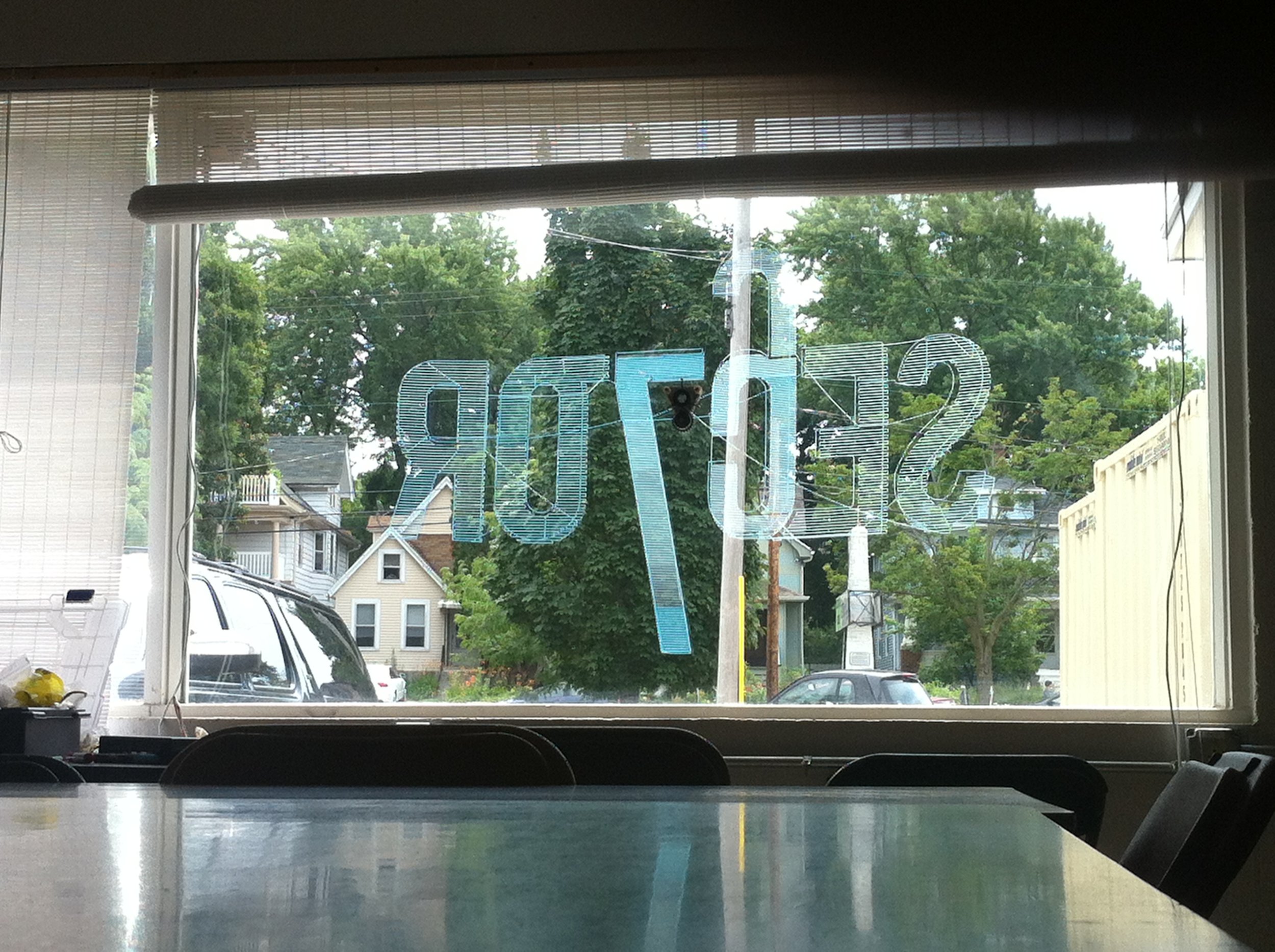
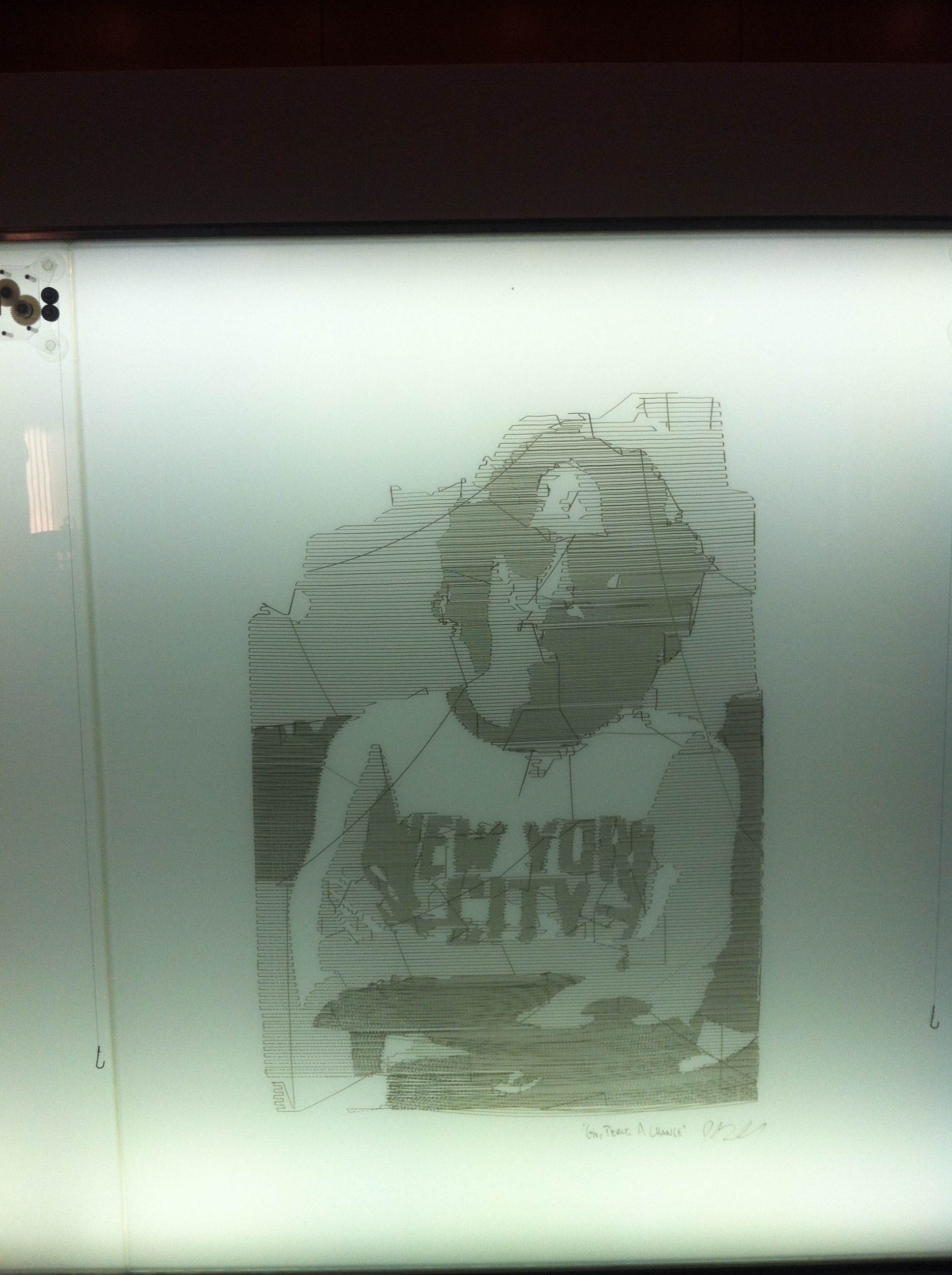
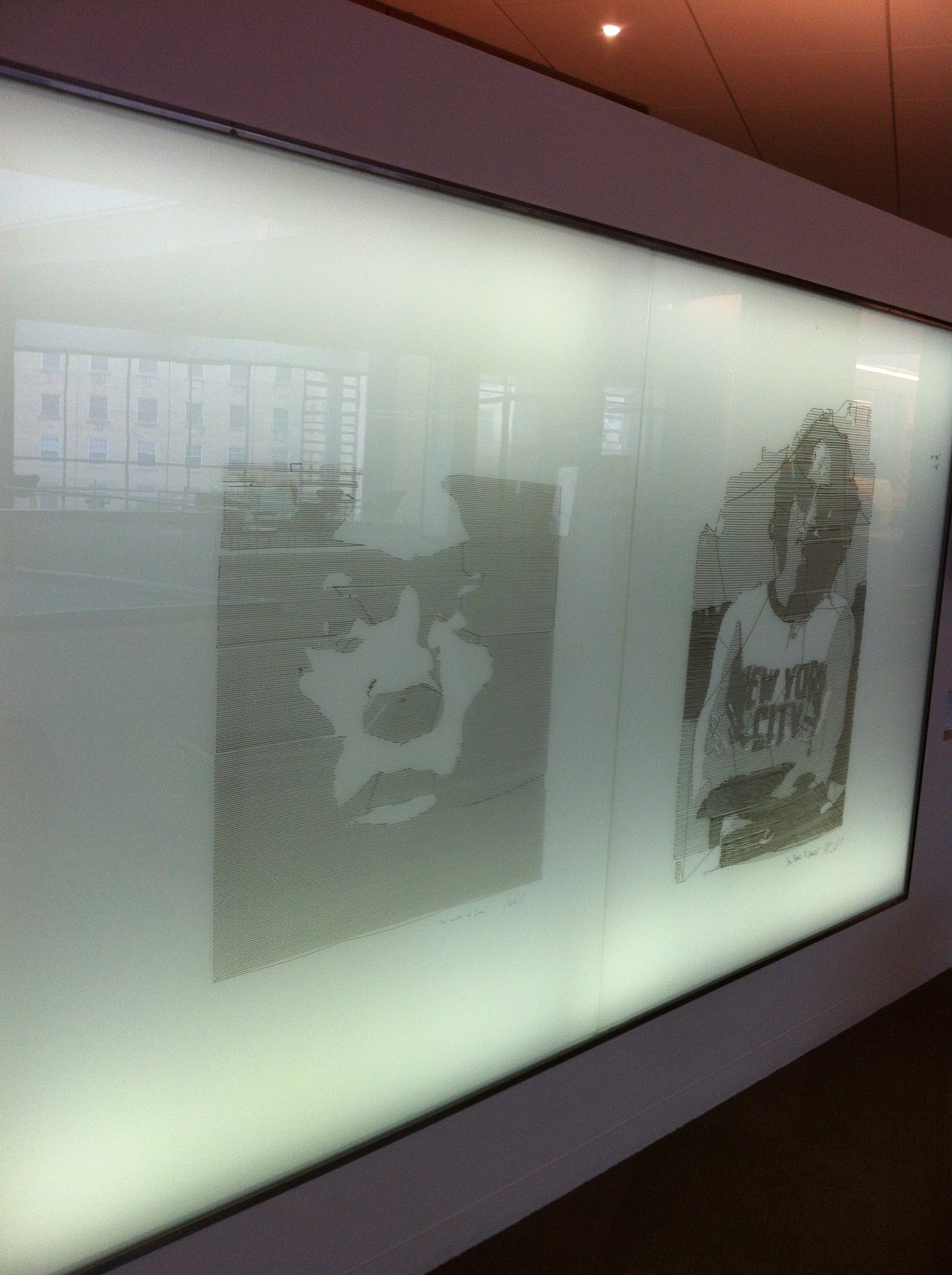
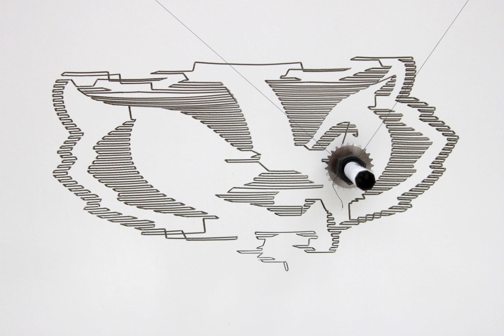
Image Processing
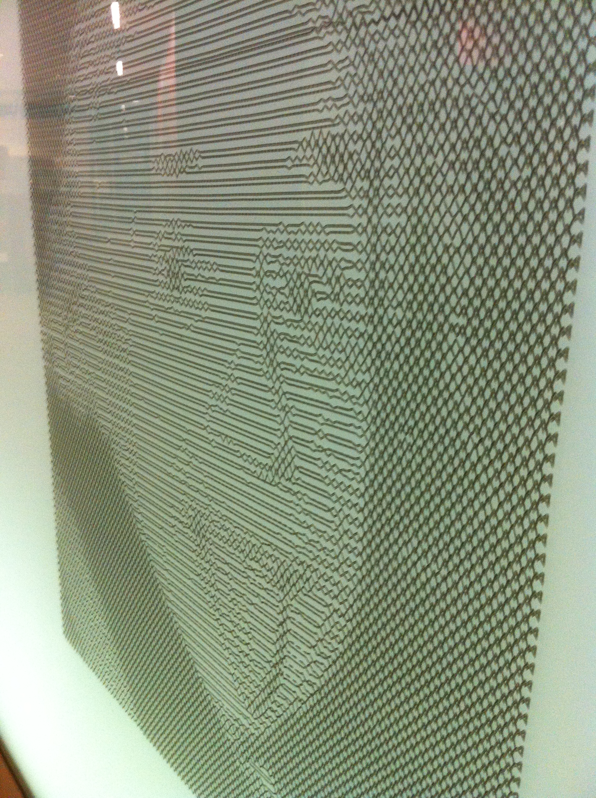
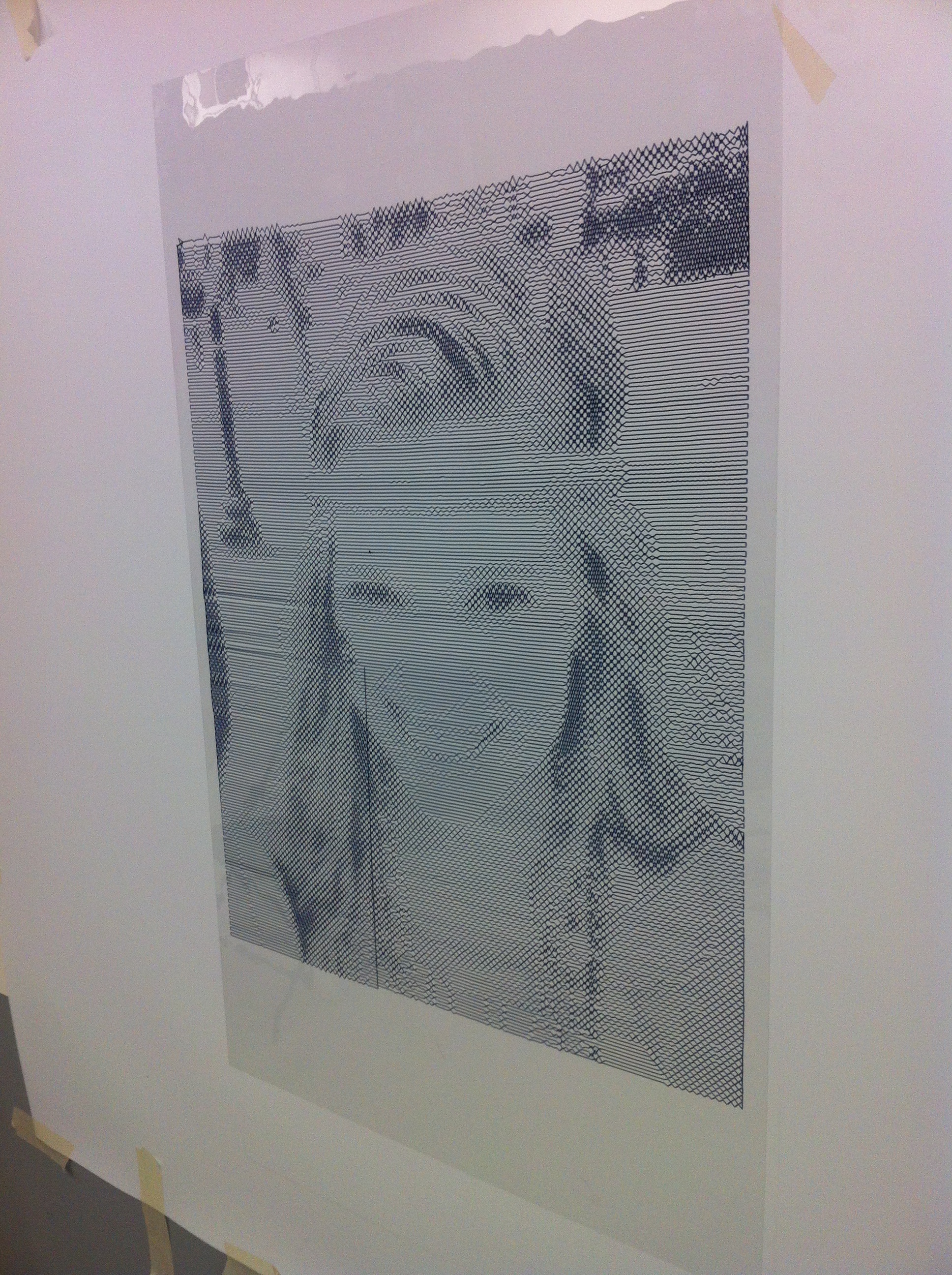
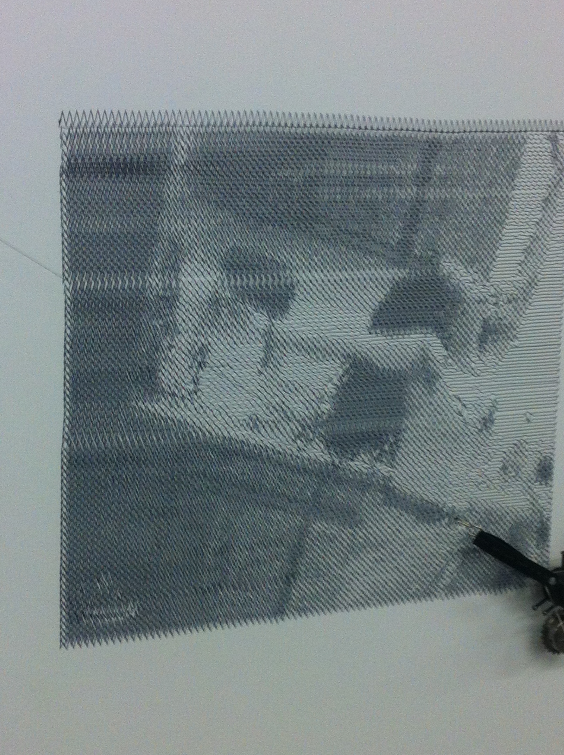
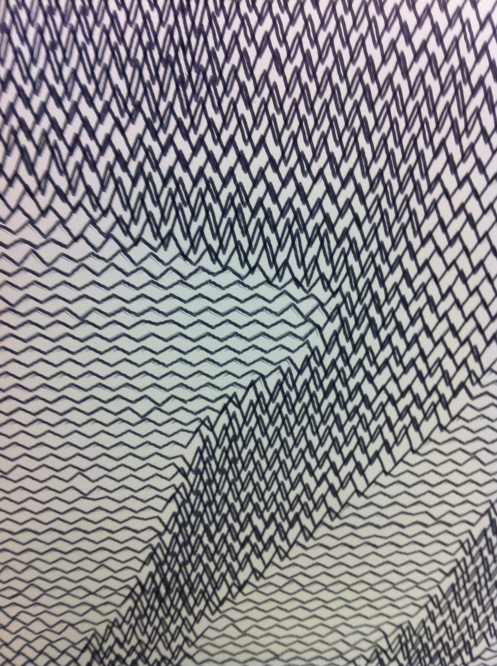
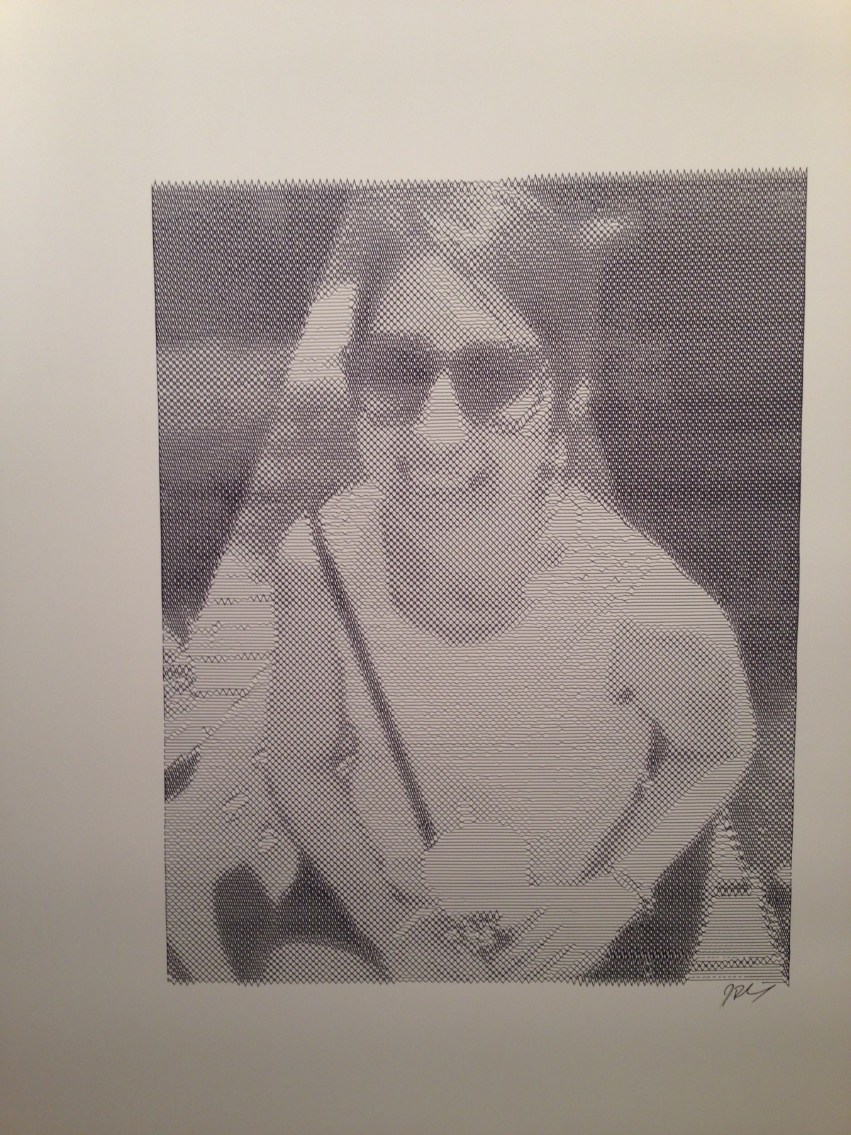
Unfortunately, since I haven’t yet made a way for the pen to push off of the surface, I decided to try my hand at some image processing that would allow me to draw an image using one continuous line segment.
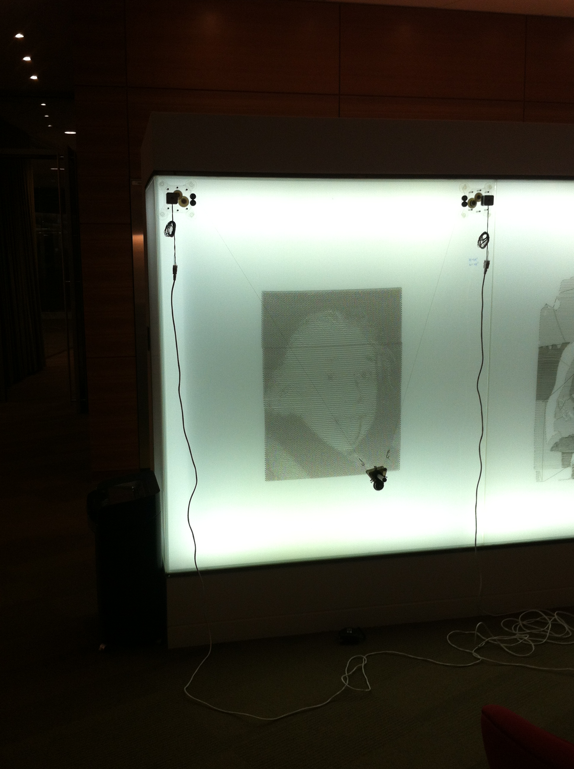
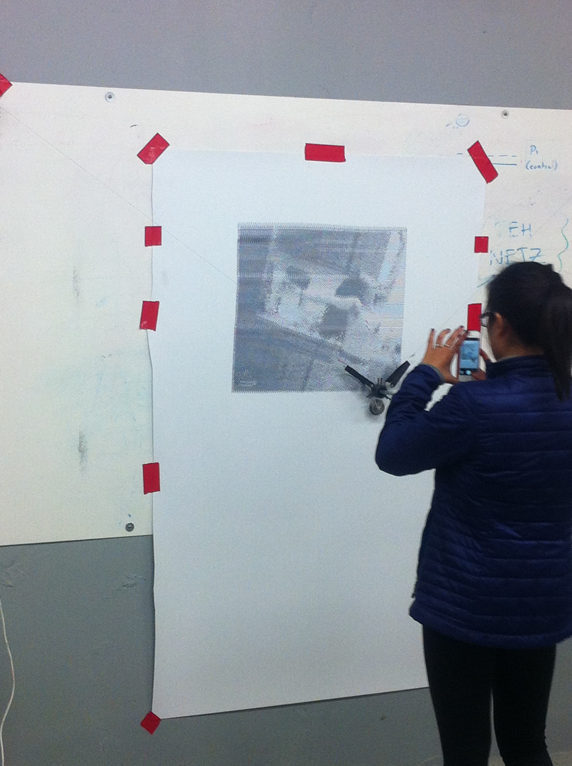
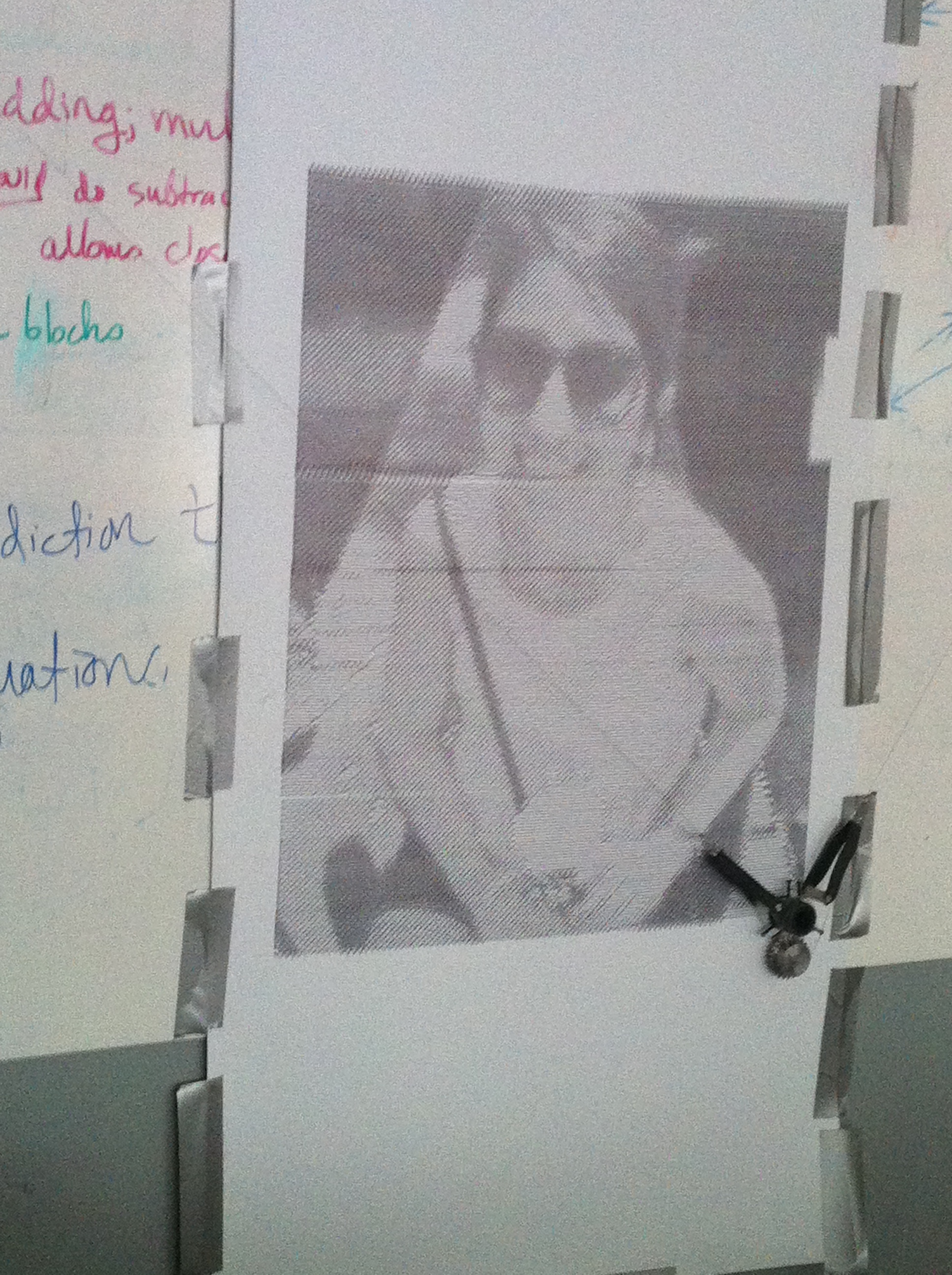
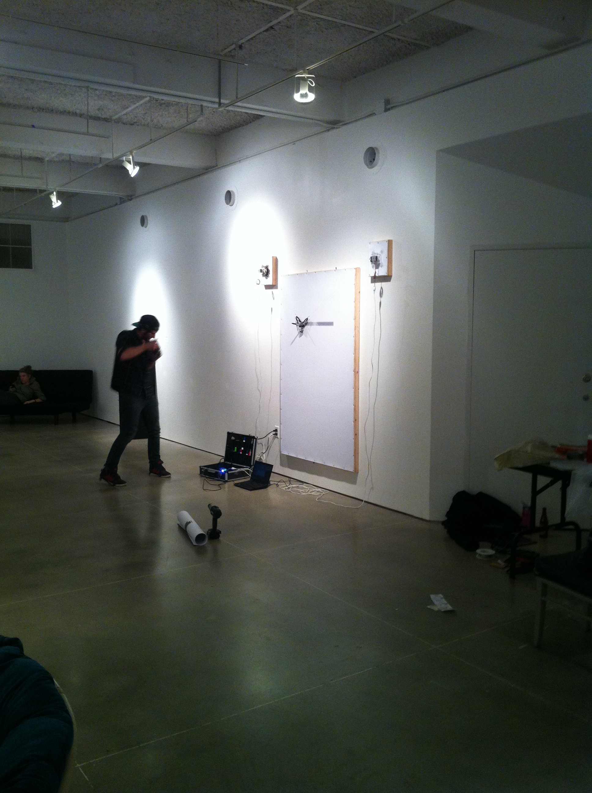
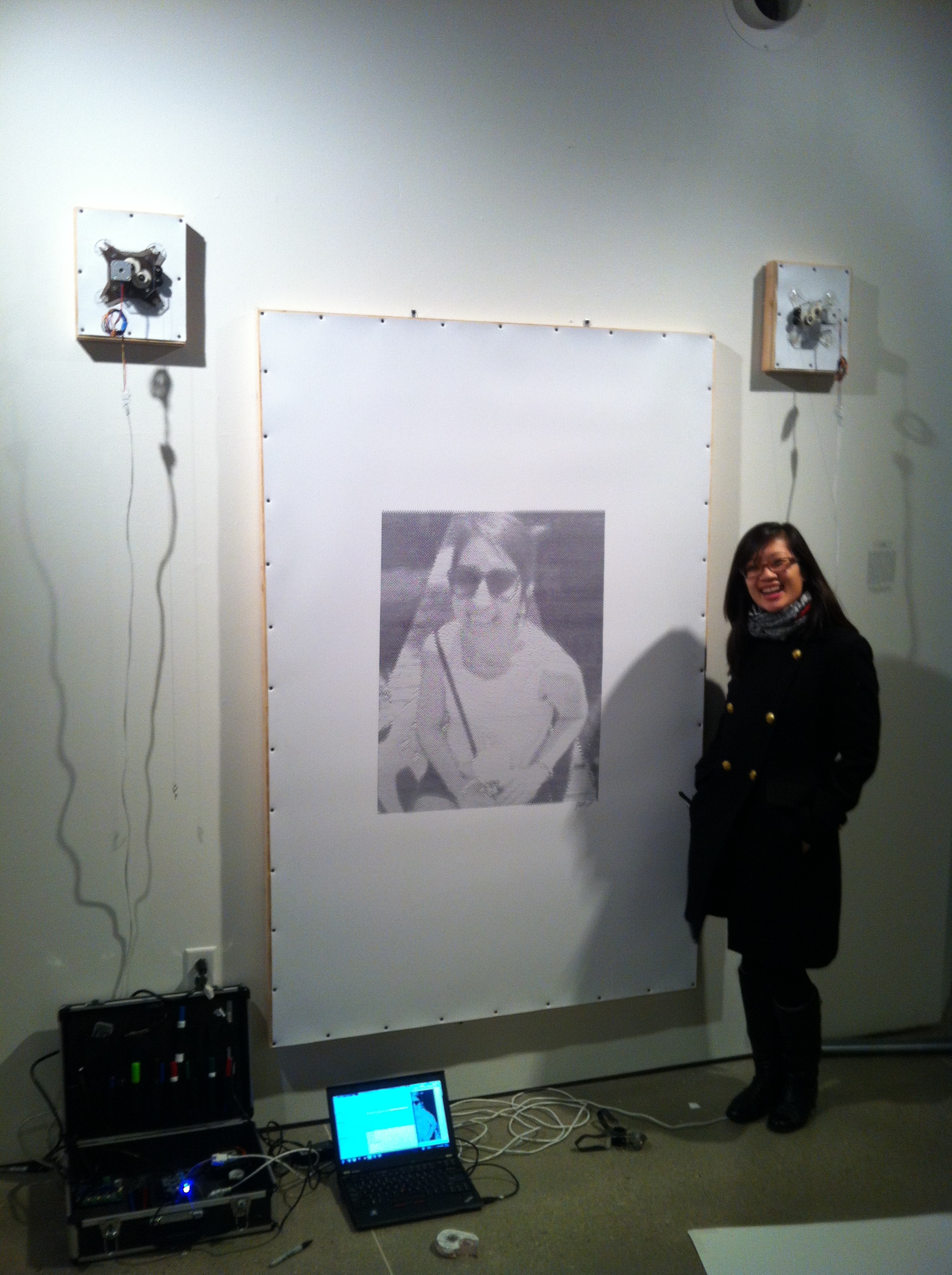
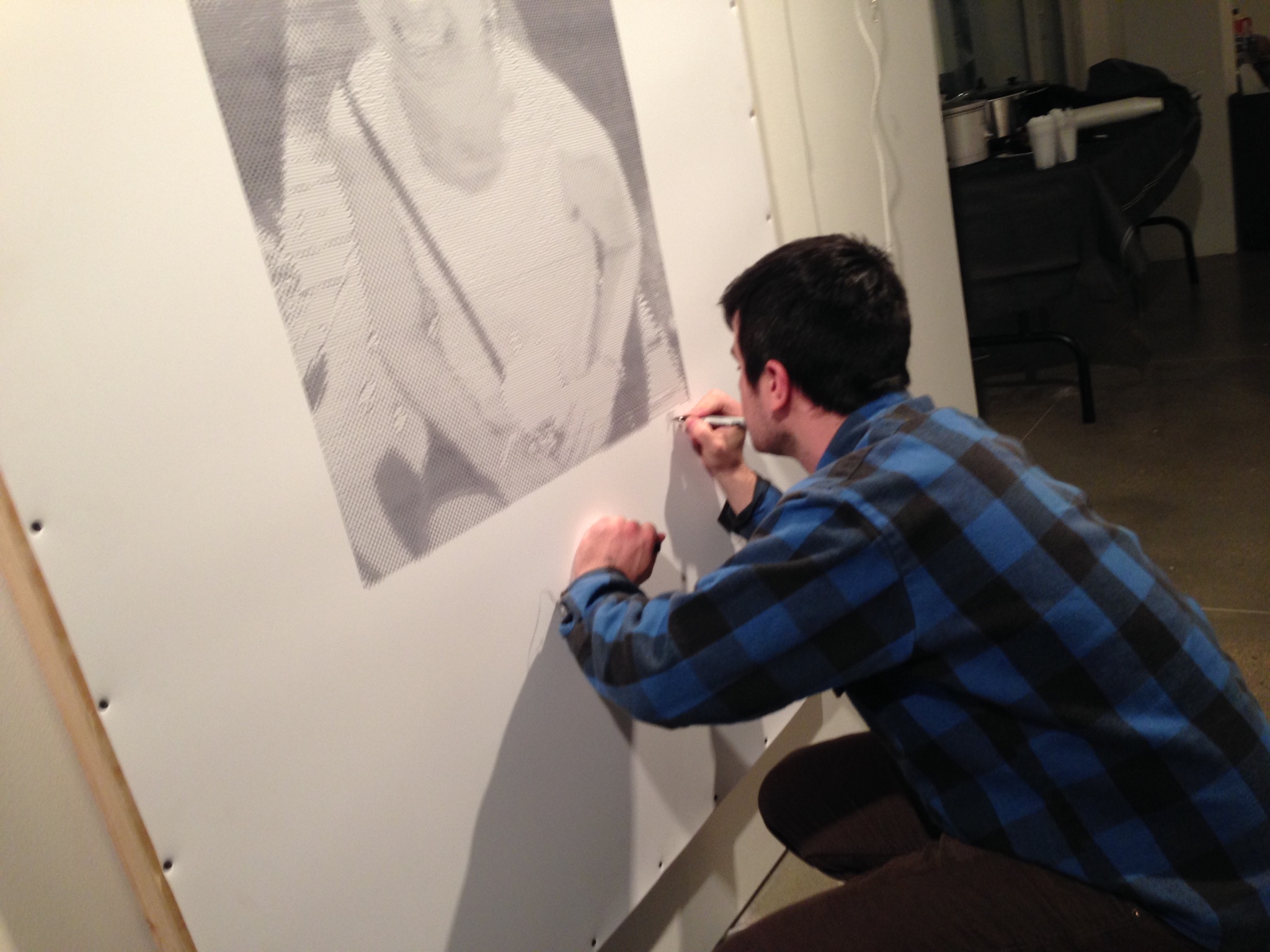
‘Believe Me’ Art Show
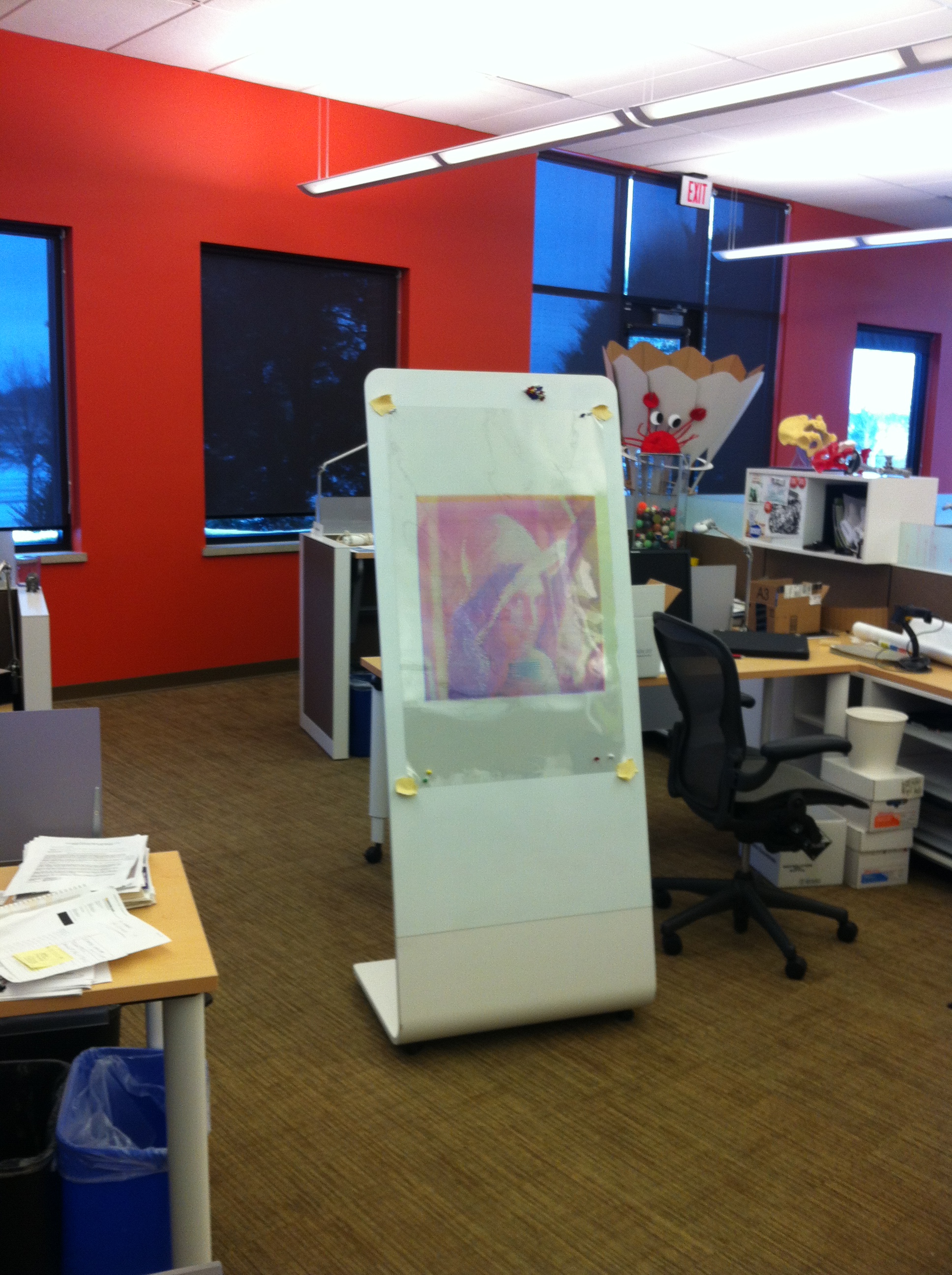
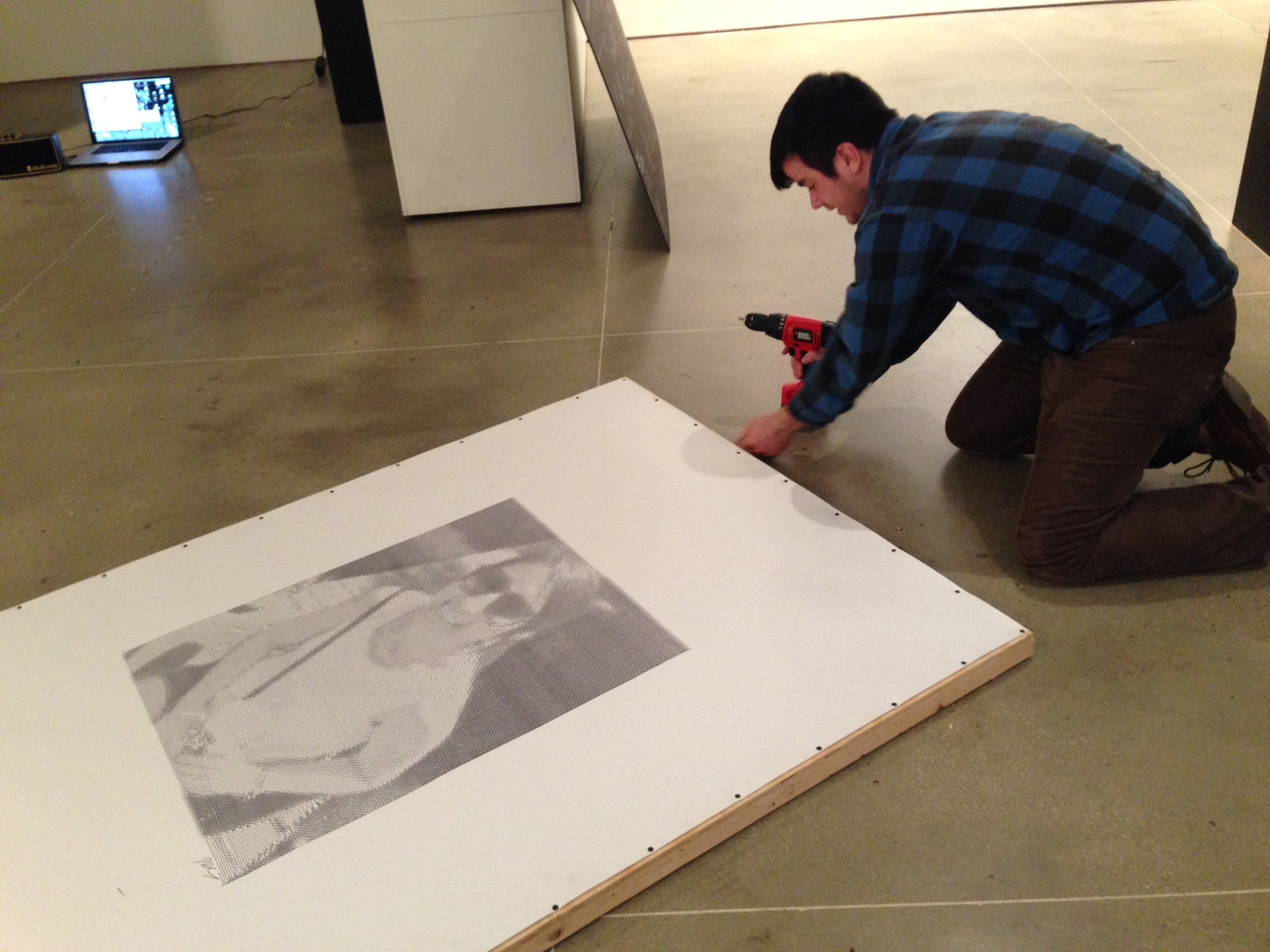
My friend Guusje was recently co-curating an art show titled the ‘Believe Me’ Art Show so I submitted the Hangbot as a dynamic installation piece. It was accepted and ran at the University of Wisconsin – Madison for a week, with a live demonstration during the closing.

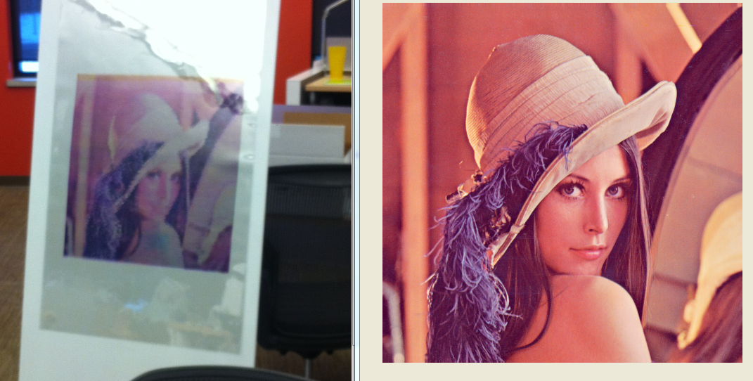
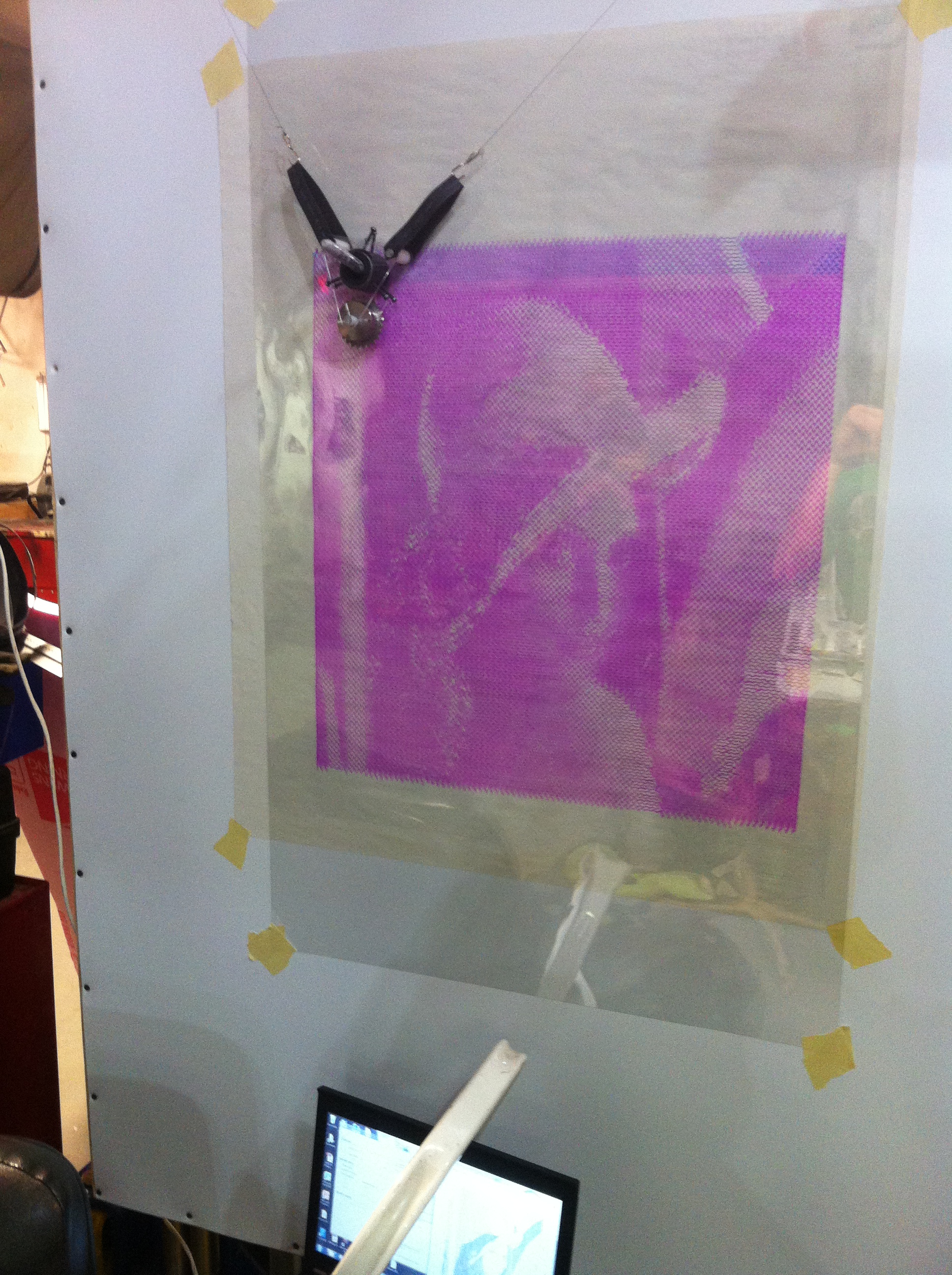
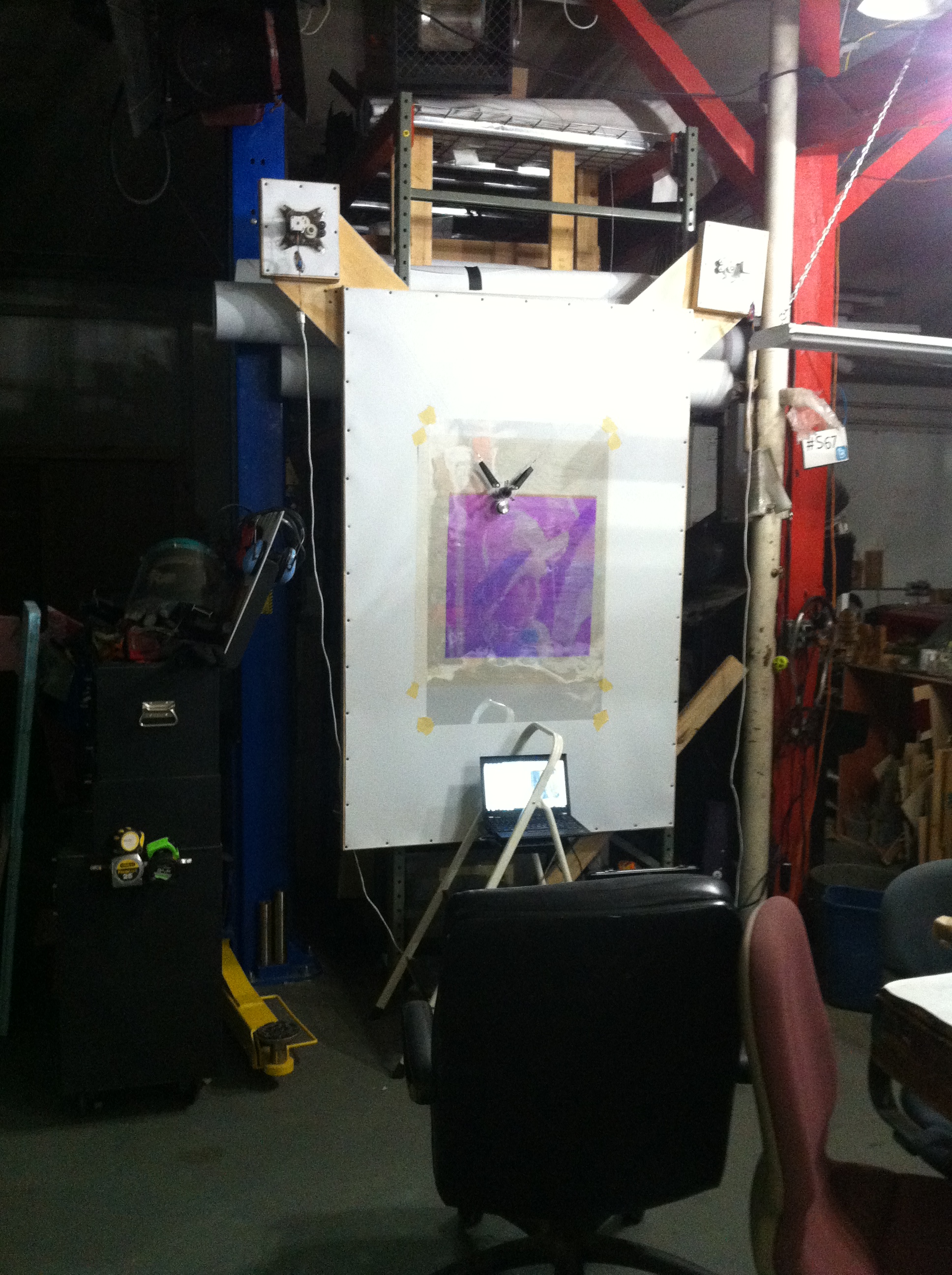
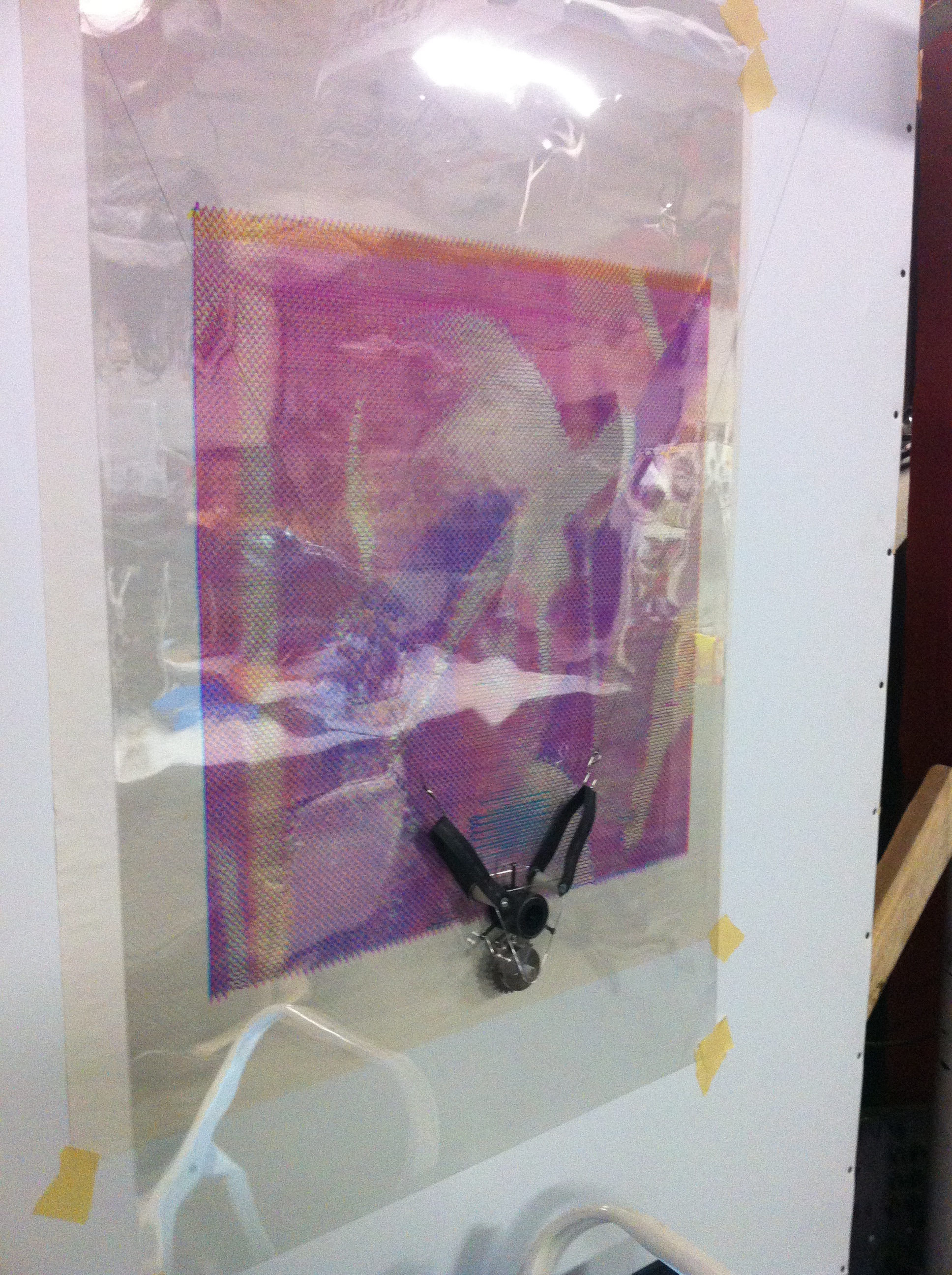
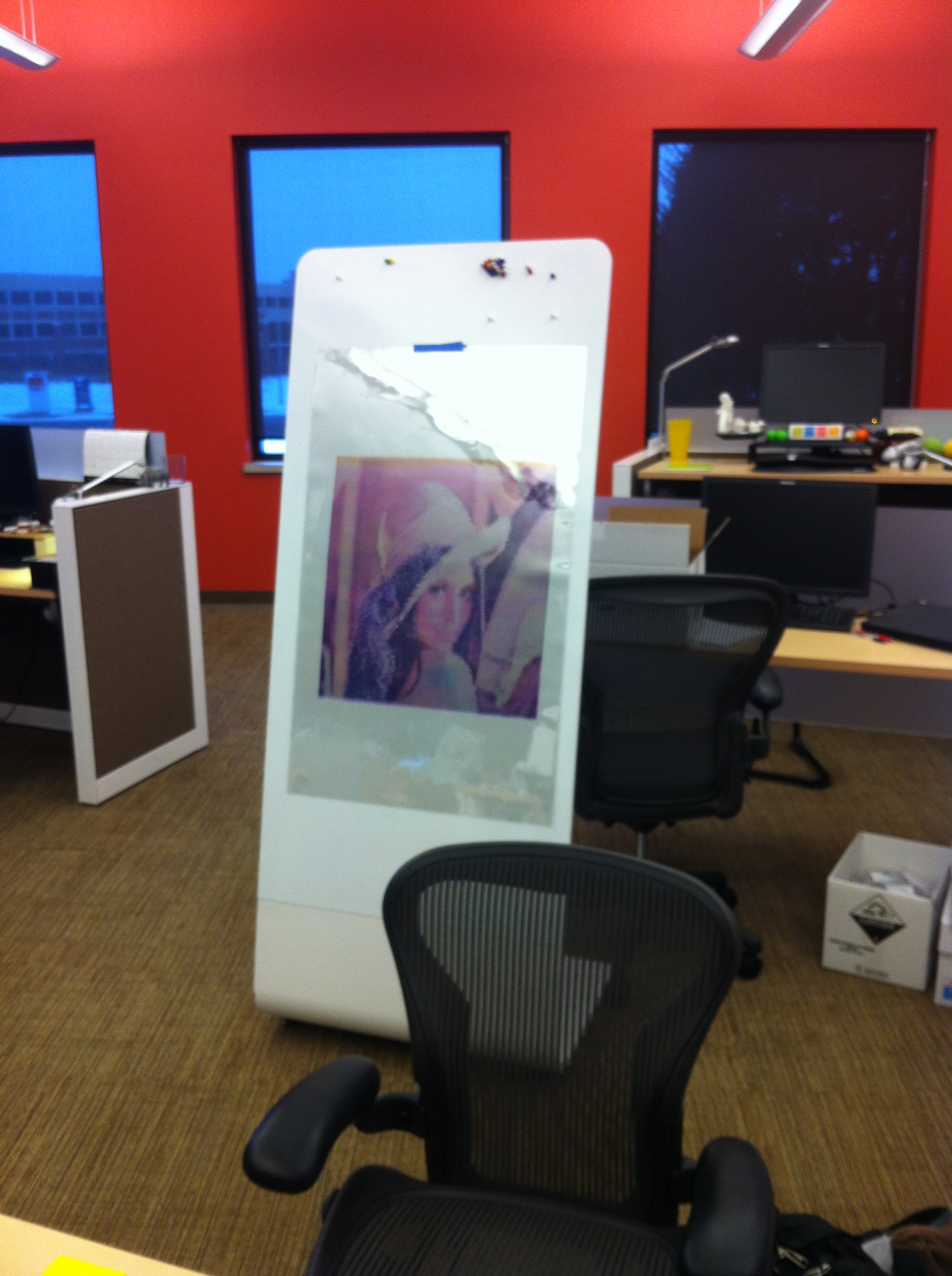
CMYK Drawings
After I had the pre-processor working well to convert images into on continuous line drawing, I wanted to try and create a color image. So I set out to draw each CMYK channel on a separate piece of clear polyester and overlay them to create a full color image.